Difference between revisions of "Set up the miniSim"
Steve Cable (Talk | contribs) (→Make the connections) |
Anna Dizack (Talk | contribs) |
||
| (119 intermediate revisions by 3 users not shown) | |||
| Line 1: | Line 1: | ||
| − | + | [[Table of contents|Table of Contents]] | |
| − | + | ||
| − | + | ||
| − | + | ||
| + | [[Introduction|◄PREVIOUS]] [[Making_the_Connections|NEXT PAGE►]] | ||
| − | |||
| − | [[Image: | + | The miniSim™ is a PC-based research driving simulator that provides a realistic automotive driving environment. The system consists of a single PC for simplicity and reliability, three front channel displays, an instrument panel display, USB steering wheel and pedals, 2.1 audio system, a tactile transducer, and a display for the operator/instructor. |
| + | |||
| + | |||
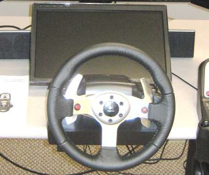
| + | [[Image:Mounetd_ECCI_wheel.jpg|400px|thumb|center|A mounted (modified) ECCI wheel]] | ||
| + | |||
| + | |||
| + | == Place the Steering Wheel and Pedals == | ||
| + | |||
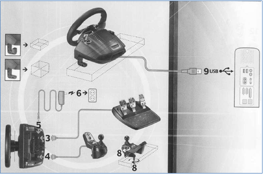
Unpack the steering wheel and pedals. Plug in the power supply, pedal, and shifter cables to the | Unpack the steering wheel and pedals. Plug in the power supply, pedal, and shifter cables to the | ||
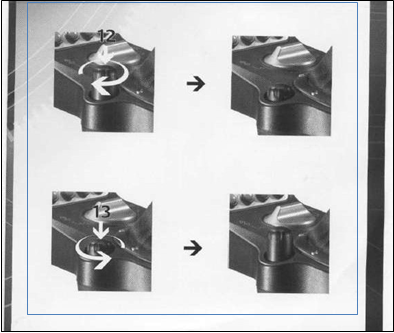
| − | underside of the ECCI or G27 wheel per the manufacturer’s instructions. | + | underside of the ECCI or G27 wheel per the manufacturer’s instructions, [[media:fi3.png|Figure 3]]. Fasten the wheel and shifter to the desktop following the manufacturer’s instructions, and place the pedals on the floor under the table, [[media:G1.png|Figure 4]]. |
| − | |||
| − | + | [[File:steeringwheel.jpg|400px|thumb|center]] | |
| − | + | ||
| − | |||
| − | |||
| − | |||
| − | |||
| − | + | [[File:MS steering wheel drawing.png|400px|center]] | |
| − | |||
| − | + | [[File:fi3.png|400px|thumb|center|Figure 3: Connecting the power supply, shifter, and pedals to the Logitech G25 wheel (from Logitech manual)]] | |
| − | + | [[File:G1.png|400px|thumb|center|Figure 4: Using the clamps to attach the shifter and wheel to the desktop (from Logitech manual)]] | |
| − | + | ||
| − | + | ||
| − | |||
| − | |||
| − | |||
| − | |||
| − | |||
| − | + | [[#top|TOP]] | |
| − | + | ||
| − | + | ||
| − | |||
| − | + | == Place the Instrument Panel Display == | |
| − | + | ||
| − | + | ||
| − | + | ||
| + | <span style="color:red;">'''CAUTION!''' Please read the warnings and handling instructions for the LCD displays located in the appendix.</span> | ||
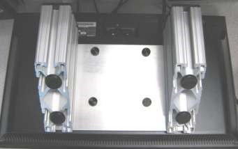
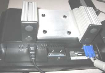
| − | + | The Instrument Panel LCD attaches to an aluminum bracket that holds the display at a 45-degree angle ([[media:Fig5.png|Figure 5]]). Mount the display to the bracket using the supplied thumb screws, being sure the display is upside down ([[media:fig6.png|Figure 6]]). Connect the power and VGA/DVI cable to the display. Place the display on the table directly behind the steering wheel ([[media:fig7.png|Figure 7]]). | |
| − | |||
| − | |||
| − | |||
| − | + | [[File:Fig5.png|400px|thumb|center|Figure 5: Underside of instrument panel display stand]] | |
| − | + | ||
| + | [[File:Fig6.png|400px|thumb|center|Figure 6: Power and VGA connections on instrument panel display]] | ||
| − | |||
| − | + | [[File:Fig7.png|400px|thumb|center|Figure 7: Location of instrument panel display]] | |
| − | + | ||
| − | |||
| − | |||
| − | |||
| − | |||
| − | |||
| − | |||
| + | In the case of the 3-channel setup with 20” LCDs, attach the LCD to the instrument panel bracket using the 4 thumbscrews. If these are lost, you may replace them with metric screws, 4mm thread and 16mm long (M4x16). | ||
| − | |||
| − | + | [[#top|TOP]] | |
| − | + | ||
| + | == Place the Front-Channel Displays == | ||
| − | |||
| − | + | <span style="color:red;">'''CAUTION!''' Please read the manufacturer’s manuals for the LCD displays located in the appendix.</span> | |
| − | |||
| − | + | Locate the three front channel displays on the tabletop behind the instrument panel as shown. Connect the video (DVI) and power cables to each monitor. The center display should be centered directly behind the instrument panel display, ([[media:fig8.png|Figure 8]]). | |
| − | |||
| − | + | [[File:Fig8.png|400px|thumb|center|Figure 8: Location of the front channel displays]] | |
| − | + | [[#top|TOP]] | |
| − | |||
| − | + | == Place the Audio System == | |
| − | + | Unpack the audio system (Logitech Z-2300). Place the subwoofer under the table, and place the two satellite speakers to the left and right of the instrument panel display, [[media:fig8.png|Figure 8]]. Observe the left and right labels. | |
| − | + | ||
| − | + | ||
| − | + | ||
| − | + | ||
| − | + | ||
| − | + | ||
| − | + | ||
| − | + | ||
| − | + | ||
| − | + | ||
| − | + | ||
| − | + | ||
| − | + | ||
| − | + | ||
| − | |||
| − | + | Connect the satellite speakers to the appropriate jacks on the rear of the subwoofer. Connect the subwoofer volume control to the subwoofer, [[media:fig9.png|Figure 9]]. | |
| + | |||
| + | |||
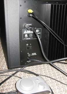
| + | [[File:Fig9.png|400px|thumb|center|Figure 9: Subwoofer connections]] | ||
| + | |||
| + | |||
| + | [[#top|TOP]] | ||
| + | |||
| + | |||
| + | == Place the Tactile Transducer == | ||
| + | |||
| + | If your simulator has a tactile transducer, first mount it under the desk under or near the steering wheel with self-drilling screws, [[media:fig10.png|Figure 10]]. | ||
| + | |||
| + | |||
| + | The tactile transducer requires a small audio amplifier (Pyle ProPCA3 shown). Connect one speaker output (Left is shown) to the terminals on the tactile transducer. Polarity (+/-) is not important. Note that we are only using the left channel of the amplifier. Use the RCA to 1/8” headphone ‘Y’ cable to connect the audio amplifier to the PC. Connect the White RCA to the Left input jack on the amplifier and plug the 1/8” headphone plug into the orange audio output on the PC. Not all Y cables are alike, so use the Realtek Audio Manager test tones to check that the subwoofer (not the center) is being used. | ||
| + | |||
| + | |||
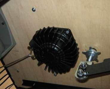
| + | [[File:fig10.png|400px|thumb|center|Figure 10: Location of tactile transducer under the desk]] | ||
| + | |||
| + | |||
| + | [[File:Figure 11.jpg|400px|thumb|center|Figure 11: Connection to Audio Amplifier. Note, the Red or White may be used, depending on the wiring of the Y cable.]] | ||
| + | |||
| + | |||
| + | [[File:Figure 12.jpg|400px|thumb|center|Figure 12: Audio Amplifier Settings: Treble fully CCW (min), Bass 3 o’clock, Volume 12 o’clock.]] | ||
| + | |||
| + | |||
| + | [[#top|TOP]] | ||
| + | |||
| + | |||
| + | == Place the Operator Display == | ||
| + | |||
| + | |||
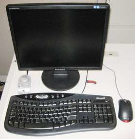
| + | Locate the operator LCD display near to the front-channel displays. The front-channel displays must be visible from the operator display, as they all form a single desktop. | ||
| + | |||
| + | |||
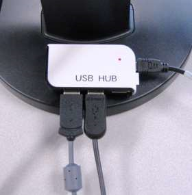
| + | Place the keyboard and mouse in front of the operator display, and stick the USB hub to the Velcro patch on the back of the display, [[media:fig13.png|Figure 13]]. Plug the keyboard and mouse into the USB hub, [[media:fig14.png|Figure 14]]. | ||
| + | |||
| + | |||
| + | [[File:Fig13.png|400px|thumb|center|Figure 13: Setup the operator display]] | ||
| + | |||
| + | |||
| + | [[File:Fig14.png|400px|thumb|center|Figure 14: Attach USB hub to the Velcro patch on the operator display]] | ||
| + | |||
| + | |||
| + | [[#top|TOP]] | ||
| + | |||
| + | |||
| + | == Place the PC == | ||
| + | |||
| + | Depending on your application, the PC may be stand-alone, or mounted in a shock-isolating rack, or mounted in a miniSim Cab. | ||
| + | |||
| + | |||
| + | The PC has three hard disks configured in a redundant array of inexpensive disks (RAID) for reliability. The technical term for this particular arrangement is a RAID5. Depending on your application, your machine may have solid-state hard disks rather than conventional hard drives. This is commonly done for mobile applications. | ||
| + | |||
| + | |||
| + | Position the PC next to the desk where the steering wheel and monitors will be placed. | ||
| − | |||
| − | + | '''CAUTION!''' Though the PC is in a shock-isolating case, it is still a sensitive and fragile piece of equipment. The primary purpose of the case is to prevent inadvertent damage during handling, not protect it against drops, slams, or rough handling. Use care! | |
| − | |||
| − | |||
| − | |||
| − | |||
| − | |||
| − | |||
| − | |||
| − | |||
| − | |||
| − | |||
| − | |||
| − | |||
| − | |||
| − | + | '''CAUTION!''' The door on the front of the PC contains a washable air filter. ''Keep the door closed during use to prevent dust getting inside the PC.'' Remove, rinse, air dry, and re-install the filter if it gets visibly dusty. A clogged air filter will reduce the flow of cooling air, and may cause the processor(s) to overheat, causing the PC to shut down. | |
| − | |||
| − | + | [[#top|TOP]] | |
| − | + | [[Making_the_Connections|NEXT PAGE►]] | |
| − | + | ||
| − | + | ||
| − | + | ||
| − | + | ||
| − | + | ||
Latest revision as of 17:44, 25 February 2017
The miniSim™ is a PC-based research driving simulator that provides a realistic automotive driving environment. The system consists of a single PC for simplicity and reliability, three front channel displays, an instrument panel display, USB steering wheel and pedals, 2.1 audio system, a tactile transducer, and a display for the operator/instructor.

Contents
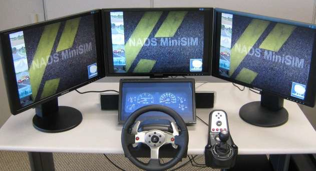
Place the Steering Wheel and Pedals
Unpack the steering wheel and pedals. Plug in the power supply, pedal, and shifter cables to the underside of the ECCI or G27 wheel per the manufacturer’s instructions, Figure 3. Fasten the wheel and shifter to the desktop following the manufacturer’s instructions, and place the pedals on the floor under the table, Figure 4.


Place the Instrument Panel Display
CAUTION! Please read the warnings and handling instructions for the LCD displays located in the appendix.
The Instrument Panel LCD attaches to an aluminum bracket that holds the display at a 45-degree angle (Figure 5). Mount the display to the bracket using the supplied thumb screws, being sure the display is upside down (Figure 6). Connect the power and VGA/DVI cable to the display. Place the display on the table directly behind the steering wheel (Figure 7).


In the case of the 3-channel setup with 20” LCDs, attach the LCD to the instrument panel bracket using the 4 thumbscrews. If these are lost, you may replace them with metric screws, 4mm thread and 16mm long (M4x16).
Place the Front-Channel Displays
CAUTION! Please read the manufacturer’s manuals for the LCD displays located in the appendix.
Locate the three front channel displays on the tabletop behind the instrument panel as shown. Connect the video (DVI) and power cables to each monitor. The center display should be centered directly behind the instrument panel display, (Figure 8).

Place the Audio System
Unpack the audio system (Logitech Z-2300). Place the subwoofer under the table, and place the two satellite speakers to the left and right of the instrument panel display, Figure 8. Observe the left and right labels.
Connect the satellite speakers to the appropriate jacks on the rear of the subwoofer. Connect the subwoofer volume control to the subwoofer, Figure 9.

Place the Tactile Transducer
If your simulator has a tactile transducer, first mount it under the desk under or near the steering wheel with self-drilling screws, Figure 10.
The tactile transducer requires a small audio amplifier (Pyle ProPCA3 shown). Connect one speaker output (Left is shown) to the terminals on the tactile transducer. Polarity (+/-) is not important. Note that we are only using the left channel of the amplifier. Use the RCA to 1/8” headphone ‘Y’ cable to connect the audio amplifier to the PC. Connect the White RCA to the Left input jack on the amplifier and plug the 1/8” headphone plug into the orange audio output on the PC. Not all Y cables are alike, so use the Realtek Audio Manager test tones to check that the subwoofer (not the center) is being used.


Place the Operator Display
Locate the operator LCD display near to the front-channel displays. The front-channel displays must be visible from the operator display, as they all form a single desktop.
Place the keyboard and mouse in front of the operator display, and stick the USB hub to the Velcro patch on the back of the display, Figure 13. Plug the keyboard and mouse into the USB hub, Figure 14.


Place the PC
Depending on your application, the PC may be stand-alone, or mounted in a shock-isolating rack, or mounted in a miniSim Cab.
The PC has three hard disks configured in a redundant array of inexpensive disks (RAID) for reliability. The technical term for this particular arrangement is a RAID5. Depending on your application, your machine may have solid-state hard disks rather than conventional hard drives. This is commonly done for mobile applications.
Position the PC next to the desk where the steering wheel and monitors will be placed.
CAUTION! Though the PC is in a shock-isolating case, it is still a sensitive and fragile piece of equipment. The primary purpose of the case is to prevent inadvertent damage during handling, not protect it against drops, slams, or rough handling. Use care!
CAUTION! The door on the front of the PC contains a washable air filter. Keep the door closed during use to prevent dust getting inside the PC. Remove, rinse, air dry, and re-install the filter if it gets visibly dusty. A clogged air filter will reduce the flow of cooling air, and may cause the processor(s) to overheat, causing the PC to shut down.
