Difference between revisions of "ISAT User Guide Table of Contents"
Shawn Allen (Talk | contribs) (→Scenario World Objects) |
Shawn Allen (Talk | contribs) (→copy/paste) |
||
| Line 626: | Line 626: | ||
===copy/paste=== | ===copy/paste=== | ||
| − | The simplest method to re-use scenario elements is copy/paste. This is possible for most scenario elements* even if the source and destination roadmap/BLIs are radically different. | + | The simplest method to re-use scenario elements among different scenario files is copy/paste. This is possible for most scenario elements* even if the source and destination roadmap/BLIs are radically different. |
| − | + | [[File:copy_paste.png|400px]] | |
| − | + | It is also possible to copy an ISAT element from one scenario to another as '''TEXT''' by selecting the element and using the windows copy shortcut CTRL-C, then open a text file and paste it using the windows paste shortcut CTRL-V. | |
| − | + | ||
| − | + | ||
'''NOTE:''' Traffic sources are '''not''' portable using copy/paste. | '''NOTE:''' Traffic sources are '''not''' portable using copy/paste. | ||
| + | |||
| + | '''NOTE:''' Not all elements can be copy/pasted. Elements created from a Create Element action cannot be copied - it is necessary to select the parent element and copy that instead. | ||
| + | |||
| + | '''NOTE:''' ISAT will not copy elements containing road coordinates (elements with a path) to a scenario that does not share the same BLI as the source (copy from) scenario. | ||
===External Reference=== | ===External Reference=== | ||
Revision as of 15:18, 21 February 2019
Contents
- 1 Who should use this document?
- 2 ISAT Overview & Interface Basics
- 3 miniSim Scenario Components Overview*
- 4 What is a Scenario Event?
- 5 ISAT Modes of Operation
- 6 ISAT Workspace
- 7 Scenario Authoring & miniSim Architecture Overview
- 8 ISAT Elements
- 8.1 ADO Scenario Object
- 8.2 DDO Scenario Object
- 8.3 DDDO Scenario Object
- 8.4 Free Motion Object
- 8.5 Static Object
- 8.6 Traffic Signal
- 8.7 Changing Signal States in Scenario
- 8.8 Virtual Object
- 8.9 Custom (icon) file virtual objects
- 8.10 Standard virtual object shape
- 8.11 Coordinators
- 8.12 Triggers
- 8.13 Trigger Operation
- 8.14 Trigger General Settings
- 8.15 Roadpad Trigger
- 8.16 Time to Arrival Trigger
- 8.17 Follow Trigger
- 8.18 Additional Triggers
- 9 Scenario World Objects
- 10 Scenario Coordinate Types
- 11 Scenario Authoring
- 12 Terminology & Documentation
- 13 Reporting ISAT & Scenario Issues
- 14 ISAT Reference Manual
Who should use this document?
Anyone learning to use the NADS Interactive Scenario Authoring Tool (ISAT) to create scenarios for simulation, or who is interested in learning more about ISAT, ISAT elements or creating scenarios.
This user guide contains an introduction to the ISAT interface and how to use ISAT for various tasks during the creation of scenario files (also known as scenario authoring).
Example scenarios are provided to help illustrate concepts and tasks.
Conventions Used in this Document
This section contains abbreviations and conventions used as a shortened description to make spelling out every step using text unnecessary.
- BLI roadmap of the road network constructed using the Tile Mosaic Tool (TMT)
- CTRL or Ctrl Press the Control (Ctrl) key
- CTL-<some other key> Press and hold the Ctrl and then press <some other key>. Most typically used for copy (CTRL-C) or paste (CTRL-V).
- LMB Left mouse button
- DblClk Double click LMB
- MMB Middle mouse button (or scroll wheel as button)
- RMB Right mouse button
Words or phrases separated by >> indicate the word or phrase after >> is a child of the word or phrase preceding these characters. For example, to describe inserting a Traffic Source in ISAT from the Insert menu:
- LMB Insert >> Coordinators >> Source >> LMB
- NOTE: LMB is assumed for all menu items and may not be explicitly included
For commands entered into a DOS command line interface (CLI) window, characters within <> are intended as generic and should be replaced in your CLI with the actual file name, without the <> characters
- <Enter> or (Enter) means to press the Enter key
Demonstration Scenarios
Demonstration scenario files have been provided to assist with learning how to use ISAT or the mechanics of specific actions or sequences of actions as examples and are not intended to be examples of completed scenarios unless identified as such.
These demo scenarios should not be considered actual scenarios, because they often lack supporting event logging (logstreams) as well as lacking any general context in terms of an overall scenario. The demo scenarios are intentionally simplistic and intended only to provide working examples of specific topics or actions.
Using Demo Scenarios
You may use the demo scenarios in ISAT for rehearsal or import and drive them on miniSim. Feel free to copy isat elements from the demo scenario files for use in your own scenarios as needed.
ISAT Overview & Interface Basics
This section contains information about ISAT and the ISAT interface.
What is ISAT?
ISAT is the NADS Interactive Scenario Authoring Tool. ISAT is used to create simulation scenarios:
- 2D roadmap viewer
- Native file format: SCN (scenario.scn)
Requires a roadmap (BLI)
ISAT is NOT:
ISAT is not an object editor for creating or modifying 3D model objects, signs or roads.
miniSim Scenario Components Overview*
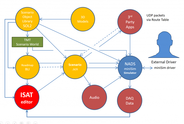
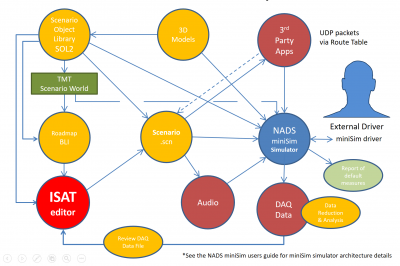
The following diagram illustrates the context of scenario authoring to provide an overview of related components.
- See the NADS miniSim user guide for miniSim simulator architecture details
TBC hyperlink to miniSim user guide & page ref
What is a Scenario?
A scenario defines everything that happens to the driver during a simulation.
Uses Actions and events to control the scenario; i.e., familiarization or restart drive, hazard detection & recognition or obstacle avoidance.
- Coupled to a roadmap (BLI)
- Scenario behaviors (responsible for executing scenarios) run at 30Hz
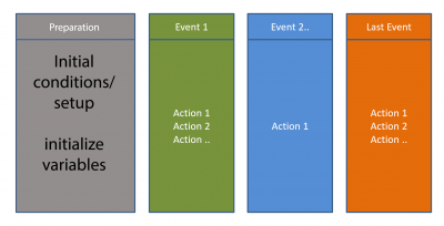
Anatomy of a Scenario
Scenarios typically have an initialization period followed by one or more events. A final event is the last event to occur before simulation is terminated.
Scenario events may contain one or more actions.
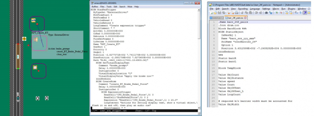
Scenario files are text files
- Can be edited by a text editor
- Portions of a scenario file can be generated programmatically:
- ISAT ISC
- Python
- Shell script
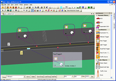
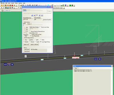
This diagram shows the same scenario in (left to right) ISAT, Emacs and Notepad++ text editors
Scenario Text File
Typically you can borrow elements from other scenario files by copying elements from one scenario and pasting them into another using a text editor or isat.
- If editing text, always check your edits in ISAT!
- Copy/Paste - delete paths from elements when the BLI is different between your source & destination BLI files:
- ADO, roadpad, time to arrival, etc.
NOTE: A Traffic Source is not a portable element
- Re-create it in ISAT or integrate it via text file
How can I find information in multiple files easily?
Text files are easy to examine in a command (shell) window.
Example search for time trigger in all scenario files: >grep TimeTrigger *.scn | grep ISAT | grep Name <Enter>
- ISAT-Samples-Avoid.scn: Name "TimeTrigger1"
- ISAT-Samples-Avoid.scn: Name "TimeTrigger2"
- ISAT-Samples-Avoid.scn: Name "TimeTrigger3"
- ISAT-Samples-Avoid.scn: Name "TimeTrigger1"
How to know what to look for in the scenario text file?
If you know what to look for in a scenario GREP can help you locate files containing that element or text quickly.
What if you don't know what to look for? How do you find something when you don't have any idea what to look for?
- Create a new scenario
- Create the scenario element you need or are looking for:
- ADO, Trigger/Coordinator
- Give the element a unique name that you can search for in the text file
- Save the file, then edit the file in a text editor
- Find the element name to see element syntax and parameters
TBC: Insert demonstration to find an expression trigger that relates to the speed of the ownship
What is a Scenario Event?
A scenario event is made from one or more actions created to present situational information to the external driver (research participant, trainee or simulation viewer) in some logical sequence;
- force a vehicle to change speed
- force a vehicle to brake, change lanes or turn
- create or destroy scenario elements
Or:
- change scenario elements:
- initialize variables
- change traffic signal state
- etc.
- change scenario elements:
Typical Scenario Events
- When the external driver approaches a specified location, cause oncoming traffic to veer into the drivers' lane to force a driver response
- As the external driver approaches a specified location, control ambient traffic to expose a vehicle stopped in the drivers' lane
- When the Time to Arrival (to a specified location) is 4 seconds, change the traffic signal to yellow and activate traffic stopped at the intersection (aka red light runner)
What is an Action?
Actions are specific commands that happen intentionally during a simulation:
- Time, situational, calculation or location based
- Caused by the external driver or some other action, hardware configuration or calculation
- can create or delete objects, including other scenario elements
Typically actions are linked with other actions to create a scenario event as shown in the figure above.
Typical Actions
- Activate a scenario element
- Calculate something:
- -Time to arrival (TTA)
- -Time to collision (TTC)
- -headway
- Check state of simulator or driver
- Create something (any scenario element)
- Destroy a scenario element
- End simulation (terminates the current drive)
- Play a sound
- Set a variable
- Set ADO vehicle speed (not the external driver)
ISAT Modes of Operation
- Edit
- Rehearsal
- DAQ playback
- Monitor Currently not available
Edit & Rehearsal Modes
- Edit - this is where scenario authors will spend the most time.
- Creation or modification of scenario
- Link to or import portions of other scenario elements
- Rehearsal
- Debug & test scenario
- Simulates scenario using Behaviors and Vehicle Dynamics
- Displays error messages from behaviors
NOTE: Rehearsal mode simulates the external driver; your simulation may not respond as expected:
- i.e., if the driver was instructed to 'remain on the right lane', the simulated ownship may not stay in the desired lane
- Some control of the simulated ownship is possible in ISAT using the Rehearsal Mode >> Advanced Options panel
- speed, lane changes
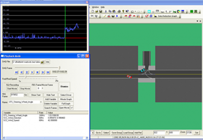
Playback Mode
- Playback mode will play back a DAQ file from a miniSim drive
- Can search for specific conditions; i.e. CFS_Brake_Pedal_Force > 0.1
- Display data streams
- Graph collected data (limited to single cells)
- Record a video file of the playback
miniSim Scenario Components
The following diagram shows an overview of scenario related components of the NADS miniSim and how these components work together.
ISAT Workspace
ISAT uses standard Windows[TM] graphical user interface conventions such as floating windows/panels/dialogs and dockable widgets.
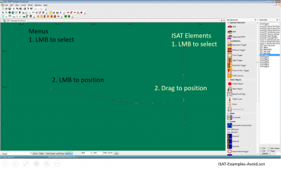
The primary region where the road network and placed scenario elements are shown is known as the workspace. In the default layout, menus are located across the top of the interface. A region of icons is located beneath the menu region. Additional ISAT widgets may be positioned along the right or left edges of the interface.
In cases where ISAT needs to place an element, notice the cursor changes to an insert element cursor when you select from menus or icons.
The menu and icon widgets require a LMB to access and place into the workspace. For the ISAT elements widget, LMB and drag the element into the workspace.
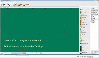
ISAT Workspace Status Bar
The status bar contains useful information to the scenario author:
- position (continuously reports location of the cursor)
When configured, the status bar can also report:
- Name of scenario elements
- Roadway information:
- road name
- default speed limit
- surface material code for location under the cursor
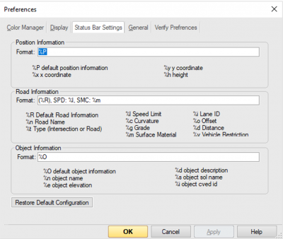
Status Bar Settings
The status bar settings can be accessed by choosing Edit >> Preferences >>Status Bar Settings. Use the existing codes to configure the status bar to display the desired information.
Measuring Distance in ISAT
To measure between two locations in ISAT:
- measurement is a linear measurement
Press & hold Ctrl and Shift keys, RMB on roadmap/BLI Position cursor over any other location
The measurement will update dynamically to reflect the distance from the cursor to the original 'pinned' location.
TBC link to video example
Scenario Authoring & miniSim Architecture Overview
This section contains scenario authoring documentation.
ISAT Elements
- ISAT objects consist of two main types: the objects that can be inserted using ISAT, and the objects already present in a roadmap/BLI.
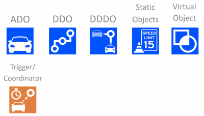
1. Objects placed in ISAT
- These are objects defined in the Scenario Object Library (SOL2) and can be placed onto a roadmap by the scenario author:
- ADO
- DDO
- DDDO
- Static Object
- Virtual Object*
- Trigger/Coordinator
- NOTE: Virtual objects are defined in the scenario, not in the SOL2.
2. Scenario world objects
- These are objects that exist in the roadmap and have not been added by the scenario author. These objects may be either authorable (can be changed by the scenario author) or not (the object cannot be selected or changed in ISAT).
- Traffic Lights
- Traffic lights are embedded into intersections for traffic control purposes.
- The SOL2 contains a traffic light object that can be placed in ISAT; this is not a traffic light that controls traffic. It is a static object that only looks like a traffic light and can be controlled like any other static object.
- NOTE: There can be only one traffic light assigned to an intersection path. In some cases, i.e. on approach to a toll booth, multiple signals may be required visually.
ADO Scenario Object
- Vehicles that use vehicle dynamics and are AI controlled
- Exceeding vehicle dynamics capability can cause issues
- i.e., if ADO must exceed 10g's, the operation will likely fail
- failure may cause ADO to disappear or be planted into the ground or fly into the air and freeze
- ADOs are 'aware' of other simulation entities
- ADOs will attempt to change lanes to go around slow moving objects if this functionality is not disabled by the scenario author
- ADOs may halt if they cannot move around a slow moving object or change lanes
- The scenario author sets default ADO behaviors; i.e.:
- initial velocity
- turn signals
- headlights
- lane changes, etc.
- RMB on ADO to specify path
TBC insert RMB ADO menu graphic
- Actions to modify ADO behavior
- Set Dial
- Set Button
- instruct the ADO to maintain distance relative to the driver
- maintain gap
- cause the ADO to do something specific; i.e.:
- enable brake light
- accelerate or slow or stop
- change lanes
- instruct the ADO to maintain distance relative to the driver
DDO Scenario Object
- DDOs are 'dumb' objects
- Do not obey traffic rules
- DDOs follow a path blindly; also known as 'path follower'
- Are not 'aware' of other entities within the simulation
- No collision detection between the DDO and other scenario elements
- DDOs have two modes of operation:
- Follow a path using kinematics
- Free motion object
- OpenDynamicsEngine library is used to model free motion objects dynamic behavior
- bouncing/rolling ball
- object falling off back of truck
- OpenDynamicsEngine library is used to model free motion objects dynamic behavior
DDDO Scenario Object
- Includes a target that affects DDO velocity/position along path
- DDDOs are 'dumb' objects
- Do not obey traffic rules
- DDDOs follow a path blindly; also known as 'path follower'
- Are not 'aware' of other entities within the simulation
- No collision detection between the DDO and other scenario elements
Free Motion Object
A free motion object is a non-vehicle DDO that:
- need to have realistic motion
- needs to interact with the environment
- simple collision detection
- objects that fall off vehicles
- static objects on road that start moving
- rolling ball (i.e., on a hill or slope)
NOTE: vehicle dynamics do not apply to Free Motion Objects
Free motion objects have 3 modes:
- coupled
- relative trajectory
- free motion
- may require a mesh file to define a portion of the road surface to react against
Change object mode using Set Dial >> DDO >> Change Mode action
TBC insert graphic
Static Object
- Model objects are defined within the SOL2
- vehicles, animals, obstacles, signs
- any model object defined in the SOL2 as a static object
- May contain multiple visual representations
- options may be set as initial condition of the object, or changed during simulation using Set Dial action >> StaticObjManager
- Can use ADO models as static objects (as defined in the SOL2)
- Not intended to move (change position) during simulation
Traffic Signal
Traffic signals are objects with special operation and function; they are coupled to intersections and routes of travel through intersections to control traffic flow similiar to their function in the real world. Traffic signals are part of the source tile model and may not be re-positioned or physically altered by scenario except for their visual signal state appearance; i.e., red, green or yellow signals.
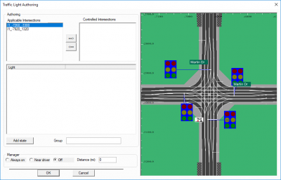
To control intersection traffic signals use Edit >> Traffic Light ManagerTraffic signals use a Signal State Table (SST) to control which signal states are active and when. Each intersection with traffic signals will have an associated SST.
The above diagram shows an intersection in the workspace to the right, and the traffic signal state table for that intersection on the left. At this point additional states (for signal condition) can be added by clicking the Add state button.
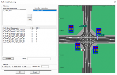
The above diagram shows two states defined for the intersection, represented by the two columns of state condition.
Continue adding states until the desired signal cycle has been defined. Generally this consists of red, green or yellow states.
NOTE: There is currently no way to automatically author a series of traffic light signals
To author traffic signal lights in sequence or on a route, the scenario author has to manage the signal states
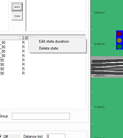
To edit the signal state duration RMB on the duration field header and choosing Edit state duration on the context menu. Enter the desired value then click OK.
Traffic Signal Types
The ISAT status bar reports Traffic Signal Type name. There are two signal types:
- Standard signal - IDs may have no identifying information
- Valid signal states: Red, Yellow, Green, Flashing Red, Flashing Yellow, OFF
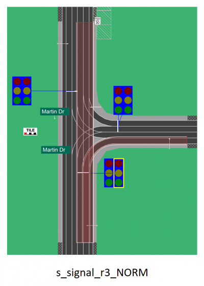
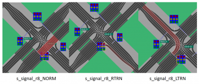
- Extended signal - The extended traffic signal type was developed to support dedicated traffic paths through intersections. These signals can be identified by the type code in their name:
- NORM (normal)
- uses standard signal states
- LTRN (Left Turn)
- signal states used should reflect signal type; i.e., Left Green, Left Yellow, etc.
- RTRN (Right Turn)
- signal states used should reflect signal type; i.e., Right Green, Right Yellow, etc.
- STRT (Straight)
- signal states used should reflect signal type; i.e., Straight Green, Straight Yellow, etc.
Changing Signal States in Scenario
Traffic signals are controlled in scenario by using a Traffic Signal Action to change the SST.
NOTE: The Traffic Signal Action works by changing the SST, not by changing the traffic signal. This is a subtle but important difference.
Setting a signal to an undefined state effectively does nothing to the traffic signal.
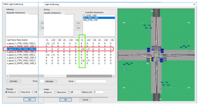
The above diagram shows a fully populated SST, with one signal row highlighted in red, and one state column highlighted in green. The associated intersection corridor is highlighted, showing the signal controls a dedicated left turn.
During simulation, the initial signal state is defined by the left column. As the simulation proceeds, the signal state changes according to the duration states defined across the state table, proceeding left to right and then wrapping around to the beginning after the last defined state. Each traffic signal appearance changes according to the configuration of the SST.
As a driver approaches this intersection, assume the signal state is in the column left of the highlighted column (Red), and the desired action is to change the signal to green.
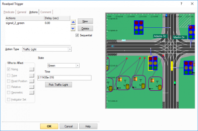
The action used to change a traffic signal state is the Traffic Light Action. Using a traffic light action requires the specification of a signal state, the traffic signal to affect, and a duration.
In the above diagram the scenario author has specified the desired state as Green as shown in the action dialog.
However, referring back to the previous state table diagram, there is no such state present in the SST. That means this particular action will fail, and the traffic signal will not change as the driver approaches the intersection - because the action does not create a new signal state, it works by advancing the state table condition (column) to the specified condition. If the condition is not present in the SST then nothing will appear to happen.
In this example, the action should be edited to use the correct signal state Left Turn Green, which is present in the SST.
NOTE: Accessing the traffic signal action after it has been created can be problematic!
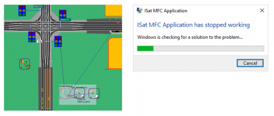
- i.e., ISAT frequently crashes when accessing the traffic signal trigger actions
Solution: Isolate traffic signal action into some other trigger, i.e. in a Time Trigger that only contains the traffic signal action. If you have to make minor edits the scenario file can be edited as text in a text editor. Major edits may require re-creating the action from scratch, if ISAT cannot access the action.
Change A Traffic Light Using Scenario Action
To change a traffic signal, use the Set Dial >> Traffic Light action. NOTE: The Traffic Light action does not change the signal directly. The action simply advances the traffic light state in the signal state table.
- If the specified target condition is not present in the signal state table, the traffic signal state does not change
This diagram shows a fully populated traffic signal state change for an intersection.
- Static object traffic lights
- These are objects, not true traffic signals and so they are not controlled with the Traffic Light manager.
Virtual Object
This object has a visual representation but does not exist as a 3D model in the simulated world
- 2D shape
- Overlay on screen of project into the scene
- supports animation (change of unique states)
A virtual object can be one of several predefined shapes or a custom image file
- Virtual objects will draw over scene elements during simulation
- Virtual objects do not render accurately during scenario rehearsal
Custom (icon) file virtual objects
Standard virtual object shape
Coordinators
Coordinators are used to control scenario elements:
- Intersection manager
- Controls traffic within intersections
- Traffic Light Manager
- Controls traffic light signal state (signal appearance)
- Triggers
- Traffic Light trigger
- Expression trigger
- Roadpad trigger
- Time to arrival trigger
- Follow trigger
Triggers
All trigger types share the same Action types
- IF Then conditional
- Predicate: i.e., the activating agent
- If predicate is TRUE, then do Action(s)
- Categorized by predicate type
- Named element
- Road (lane)
- Nth vehicle on path only
Trigger Operation
One shot
- Fire trigger once only
Debounce
- Debounce is the interval between multiple trigger activations when predicate is TRUE and actions have completed execution
- Controls the 'rate of fire' of the trigger
- Debounce prevents unintentional repeat execution of the trigger actions
For example, a time trigger with a debounce of 0.96 seconds and actions that take 1 frame to complete will fire once per second.
Trigger General Settings
- Lifetime
- How long the trigger is alive (active)
- Default 0 means trigger lives unless the trigger is deleted
- Activation Delay
- Time after the trigger is created when it becomes active
- Creation Radius
- How close the external driver has to be to the trigger before it is created
- Delete trigger when the external driver is no longer within the distance specified
- One shot
- Fire the trigger only once
- Priority
- Used with interdependent triggers to establish trigger priority:
- i.e., a roadpad trigger sets a variable, and an expression trigger reacts to that variable. The roadpad trigger should have a 'high priority', the expression trigger should be set to 'Low priority'.
- Debounce
- Time after firing the predicate remains inactive
Roadpad Trigger
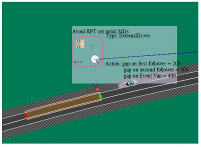
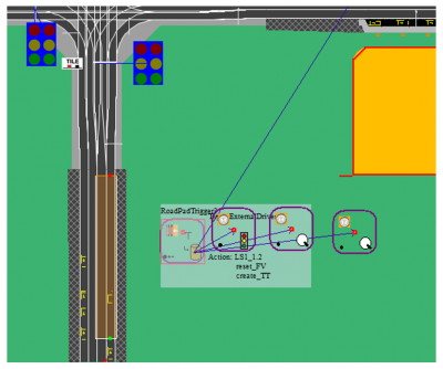
A roadpad trigger (RPT) is defined on a segment of road or intersection by a path called a road pad (or pad).
The roadpad pad defines a geographic region where the trigger can be activated.
The trigger activates when the trigger predicate steps on the pad anywhere on the pad. It is not necessary for the trigger predicate to step on the pad at the beginning (start) of the pad.
- By Name Set
- ISAT will prompt for existing scenario model object/s
- By Type Set
- Type of object; i.e., External driver, ADO, etc.
- By Road
- Filter trigger to a specific lane; i.e., predicate has to be on the roadpad and in target lane
- Can be used to implement conditional trigger activation
- An audio message to change lanes can be suppressed if the driver is already in the correct lane
TBC insert Road Trigger dialog graphic
Time to Arrival Trigger
The Time to Arrival Trigger (TTA) is similar to the Roadpad Trigger and adds a timer
- Time to reach target point
- Can use an expression to calculate time
- Arrival time can take acceleration into account
Target point
- The location used to measure vehicle distance
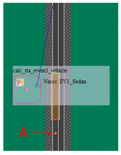
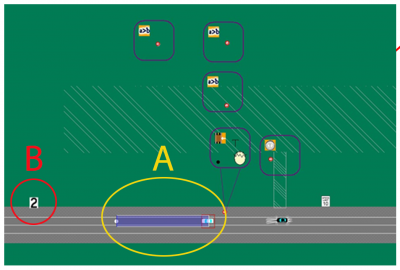
Time to Arrival Trigger example
A is the target point used in the trigger calculations
Follow Trigger
The Follow Trigger (FT) is another type of roadpad trigger
- Trigger activates when vehicle A is Distance X from vehicle B
- Distance can be in feet or time
- Both vehicles must be on roadpad;
- very long roadpads are common with this trigger
- Vehicles can include the External Driver
- Expression takes priority over time field
TBC FT graphics
Additional Triggers
- Global Time (GTT)
- Elapsed time from start of scenario
- To use GTT as a timer, add an Activation Delay set to the desired elapsed time
- Expression Trigger (ET)
- Execute actions if input expression evaluates to TRUE
- Traffic Light Trigger (TLT)
- Execute actions when target traffic signal is set to target state;
- when the traffic signal state matches the target state, execute actions
Scenario World Objects
Scenario world objects are defined in the tile model source. They are not added by the scenario author since they are objects already present in the roadmap/BLI.
Typically, but not always, these objects can be authored in ISAT. However, some scenario world objects have no options - these cannot be selected in ISAT; therefore such objects cannot be authored.
Removal of world objects requires editing the source tile model using a 3D application. In some cases an alternate tile model is available identical to the original but without objects.
Contact NADS if removal of a world object is needed.
Other scenario world objects, such as Traffic Signals, are specialized function objects that can be authored. Traffic signals are authored using the Traffic Light Manager: Edit >> Traffic Light Manager.
Scenario Coordinate Types
There are two types of coordinates used in scenarios. The first is roadway coordinates. These coordinates are contextual (tied to a specific road or intersection and position) and are used for ADO objects and roadpad paths in general.
After a roadway coordinate has been generated, it is not updated unless the scenario author makes changes to the start, end or location of the entire path or pad.
Roadway coordinate are the reason it is not possible to change a roadmap using the TMT and expect a previously authored scenario to work on the altered roadmap. If the length or location of a road changes, the path/pad will update to the extent possible.
If the road has been eliminated and no longer exists in the roadmap/BLI, ISAT will report an error and not open the scenario file.
A. Field breakdown: RoadPos keyword <name of road:lane:position on road:path length>
Name "Ado1"
 RoadPos "r1_-6600_4620:0:5737.06:0.00"
 Path "R:r1_-6600_4620:0[5736.06:5873.83]"
B. Name "VirtObj"
 Option 2
 Position -6.8375599E+002 5.6331237E+003 0.0000000E+000
The second type is world coordinates, which are Cartesian coordinates with X increasing to the right, Y increasing forward, and Z increasing up.
Scenario Authoring
Scenario authoring is the creation, editing and testing of everything that happens during a simulation drive.
All scenarios designed to be driven require a start location - the place where the driver will be located when the simulated drive begins.
To insert a start location into a scenario:
- Insert >> External Driver >> LMB on road, intersection or terrain object
NOTE: scenarios that contain data - for example, signs or traffic that are used as external reference files do not require a start location, since that will be defined for the parent scenario.
Initial Conditions
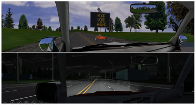
Initial conditions define how the simulated scene is configured: will the drive occur during daylight or night time conditions? Will the ownship (external driver vehicle) have headlights enabled? What type of vehicle will it be? Will there be objects or traffic visible to the driver? These form the initial conditions of the simulation experience. Additional initial conditions would include initialization of variables or establishing networked communication as needed by the scenario.
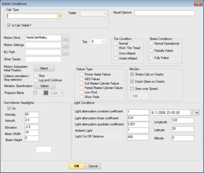
By default ISAT sets the initial condition Time of Day to 12:00 noon. The time of day is controlled from the Initial Condition dialog:
Edit >> Initial Conditions
Re-use of Scenario Elements
Scenario authoring can be an intensive undertaking. It makes sense therefore to leverage your development efforts by re-using scenario elements where possible.
ISAT provides a number of ways to re-use scenario elements:
- copy/paste
- external references
- exporting elements as groups
- isc scripts
Each of these methods have their strengths and weaknesses.
copy/paste
The simplest method to re-use scenario elements among different scenario files is copy/paste. This is possible for most scenario elements* even if the source and destination roadmap/BLIs are radically different.
It is also possible to copy an ISAT element from one scenario to another as TEXT by selecting the element and using the windows copy shortcut CTRL-C, then open a text file and paste it using the windows paste shortcut CTRL-V.
NOTE: Traffic sources are not portable using copy/paste.
NOTE: Not all elements can be copy/pasted. Elements created from a Create Element action cannot be copied - it is necessary to select the parent element and copy that instead.
NOTE: ISAT will not copy elements containing road coordinates (elements with a path) to a scenario that does not share the same BLI as the source (copy from) scenario.
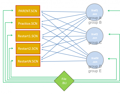
External Reference
An external reference scenario is intended to be re-used by multiple 'parent' scenarios. The effort of authoring objects is thus leverages across multiple files, without needing to re-create the same elements more than once.
Common uses of external references include traffic, traffic signal operation, traffic sign appearance or other environment features which have multiple appearances (billboards, some tile related scenery, etc).
NOTE: Multiple external references are possible; but because objects are categorized by group, it is not entirely necessary.
For example, one external reference file contains traffic, another contains signs. These two external reference scenarios could be combined into one file.
NOTE: Each group defined must be unique across all files: parent and external reference files.
In order to use an element in an external reference scenario, it is necessary to define and assign a group to all elements that you wish to control from the parent scenario. At this time there is no visual hint in ISAT to indicate if a group has been assigned to an element or not - each element has to be confirmed independently.
However, a properly authored external reference element cannot be edited within the parent scenario (after you have done Add Ref. to use the external reference file).
An alternative is to insert groups using a text editor with macro capability, or to use a program or external script to make the necessary changes.
NOTE: At this time there is a known issue using the write cell SCC_Audio_Trigger action in external references. Although the trigger containing this action can be assigned a group and used as an external reference, audio does not play.
Because ISAT updates static object positions (elevation) to the terrain (roadway) when the scenario file is saved, the best way to use a custom elevation is to put such objects into an external reference file.
Define a Group
RMB on the element and choose from the context menu: Group >> New Group (if this is a new group) or Group >> (choose an already defined group).
NOTE: The first time you create a group for an object, ISAT will automatically assign the group to that object.
After defining and assigning groups to the scenario elements needed, save the scenario file then close it.
Open or create the parent scenario file and use the Add Ref. button at the bottom of the ISAT window to select your external reference scenario. After you choose a file ISAT will present you with the groups found in that scenario. Choose the groups you with to include and click the 'Okay' button. Click the Add Ref. OK button to complete the process.
NOTE: ISAT does not enforce logic on your external reference authoring. If you add references to scenarios that do not share the same roadmap/BLI as the parent scenario, it is likely that elements will be placed at the origin (in cases where the external reference roadmap contains roadways not found in the parent).
Exporting ISAT Elements as Groups
Transferring ISAT elements among scenarios can be accomplished using groups. As with external reference scenarios, one or more groups must be defined and then assigned to one or more elements.
After defining and assigning groups select the group for export using the Group select drop-down located at the lower left corner of ISAT. Choose a group to export and then click the 'Save Group' button. Save the file.
TBC insert graphic sequence diagram here
NOTE: If you cannot locate the group file in the folder specified, check the ISAT install\data folder. This is typically:
C:\NADS\ISAT\data
Group File Contents
The group file is a text file and can be opened or edited in a text editor.
The following is a group file containing one ADO. Note the GroupName line near the bottom:
Header
 LriFile "_dev.bli"
 LongComment "this is a test group export"
 ShortComment "this comment was left empty"
&&&&End&&&&
HCSM Ado
 RunMode "eREMOTE_CONTROL"
 RandomSol 0
 Name "Ado1"
 DynModel "Non Linear"
 LogFile ""
 LatOffsType 0
 CreateRelLatInFeet 0
 CreateRelOffsLonUsingExpr 0
 CreateRelOffsLonExprStr ""
 AutoControlBreakLights 0
 AutoControlHeadLights 0
 UseReaDel 1
 StdToAccType 0
 StdToDecType 0
 StdToDecVal1 9.0000000E-001
 StpToAccType 0
 DecToAccType 0
 FollowTimeMin 1.0000000E+000
 FollowTimeMax 2.0000000E+000
 EmergDecClip -1.1000000E+001
 Accel2Catch 0
 NormVel2Kp 7.0000000E-001
 PathSearchDepth 2
 LcvFall 1.5000000E+000 2.0000000E+000
 LcvFreq 3.0000000E-002 5.0000000E-002
 LcvRAmpl 1.0000000E-001 5.0000000E-001
 VelCtrlInitMatchOvVel 0
 VelCtrlFollowSpeedLimit 0
 VelCtrlDistType 0
 MaxLatOffset 9.0000000E+000
 LongComment " "
 ShortComment " "
 SolName "Audi"
 RoadPos "r1_1320_44220:2:32414.44:0.00"
 GroupName "TEST_Group"
&&&&End&&&&
HCSM StaticObjManager
&&&&End&&&&
HCSM DriverMirror
&&&&End&&&&
HCSM IntersectionManager
&&&&End&&&&
ISC Scripts
Scripts are an efficient way to automate repetitive and/or complex tasks.
ISAT uses a custom language (ISC) to automate placement and manipulation of scenario objects. Combined with simple direction commands and the capability to navigate a road network, ISC scripts can ask the scenario author for input and prompt for selecting objects.
ISAT installs with some ISC script files. If your version of ISAT contains a data\isc
folder, then your version of ISAT is capable of running scripts. You can create
additional scripts as needed. All scripts located in the data\isc folder will load in ISAT
when ISAT is launched.
You can use these scripts for reference in creating your own custom scripts.
New scripts created during an existing ISAT session will not appear until ISAT is re-
launched.
Scripts that have been edited will not update until ISAT is re-launched.
Unless otherwise indicated, scripts are case-sensitive.
NOTE: Please do not edit the existing scripts!
Make a copy of any existing script before you make changes. In the event your modified script does not work, you can look at the original file for reference.
ISC scripts are located on the ISAT Elements widget. Custom isc scripts are located after the 'Events' separator.
Using an ISC script involves LMB + dragging the desired script onto the workspace. In some cases the script will ask for inputs.
ISC can be also used to create an entire event, thus ensuring that all events created will be entirely identical in terms of settings and locations for all created elements.
ISC scripts are text files located within the ISAT installation data folder. Only the custom ISC scripts are located in this folder. This is typically:
C:\Nads\Isat\data\isc
Icon Files
Script icon files are 8-bit windows icon files (file.ico). GIMP is capable of exporting valid ico files. To create an ico file, scale it to 32x32 pixels. Export the file as .ico to the isat\data\isc folder.
In order for a script to use an icon file, both files must exist in the isat\data\isc folder.
ISC Script Examples
This section contains example scripts with notes.
Rotate sign
.Name SetSignRotation
.Icon SignRot.ico
Static sign
Select(sign,"Please Select a Sign")
sign.SetAngle(Anchor)
.End
Place Multiple Static Objects (TrafCone) The following script asks the scenario author for number of cones to generate, position and offset values and then generates the objects.
A breakdown of the script follows the code block below.
.Name Cones
.Icon cone.ico

Block coneBlock %%%
HCSM StaticObject
  IsNewObj 1
  Name "Cone_xxx"
  SolName "TrafCone"
  Option 0
  Position 3.4312599E+002 -7.2408282E+004 0.0000000E+000
&&&&End&&&&
%%%
Static cone;


Value	dist1
Value	numberOfCones
Value	distance
Value	variablePart
Value	randDistance
Value	speed
Value   Count
Value	LatOffset

Block tempBlock
tempBlock = coneBlock
Count = 1
tempBlock.Replace('xxx',Count)
cone.SetBlock(tempBlock)

Ask(numberOfCones,"How many cones?" )
Ask(dist1,"Distance between cones?" )
Ask(LatOffset,"How much offset?" )

Position posRp
Position tempPos
posRp = Anchor
numberOfCones = numberOfCones

Repeat numberOfCones
	posRp.GoForward(dist1)
    # test comment
	tempPos = posRp;
	tempPos.SetOffset(LatOffset)
	cone.RoadPos = tempPos
	cone.Clone
    Count = Count + 1
    tempBlock = coneBlock
    tempBlock.Replace('xxx',Count)
    cone.SetBlock(tempBlock)

End
.End
Breakdown of script cones.isc
This section contains a description of the elements used in the script. The script segment is followed by a brief text description.
This script places a number of object copies (TrafCone) using information provided by a user.
.Name Cones
.Icon cone.ico
The first line contains a keyword .Name followed by the name of the script. This is the name that ISAT will use on the Isat Elements widget for the script. Note the script name does not have to be the same, but it is good computing practice.
The second line begins with the keyword .Icon followed by a file name. This file must exist in the ISAT\data\isc folder (accompanying the script file). This is the icon ISAT will use for the script.
Block coneBlock %%%
HCSM StaticObject
  IsNewObj 1
  Name "Cone_xxx"
  SolName "TrafCone"
  Option 0
  Position 3.4312599E+002 -7.2408282E+004 0.0000000E+000
&&&&End&&&&
%%%
This is the data section of the script, which is defined using the keyword Block. A block name follows the keyword, and the data start is defined with %%%.
The HCSM StaticObject section has been copied from a scenario. In this case, a static object was placed into the workspace and then copied into a text file.
Name "Cone_xxx"
Note: the object name contains a marker that can be used to programmatically name instances of the object:
SolName "TrafCone"
This line begins with the keyword SolName followed by the name of the object as it is defined in the sol2.txt file.
Position 3.4312599E+002 -7.2408282E+004 0.0000000E+000
The Position of the static object will update when the script activates and instanced objects are placed in the workspace.
Static cone;
This line begins with the keyword Static followed by a variable name.
Value	dist1
Value	numberOfCones
Value	distance
Value	variablePart
Value	randDistance
Value	speed
Value   Count
Value	LatOffset
This section defines variables with the keyword Value followed by variable names. Using descriptive names is better than generic names. From the variable list it already seems clear what the programmer cares about: number of cones and distances.
Block tempBlock
tempBlock = coneBlock
This section defines a block using the keyword Block followed by the variable name.
The next statement replicates coneBlock into tempBlock.
Count = 1
Initialize the value of the variable Count to 1.
tempBlock.Replace('xxx',Count)
The built-in Replace function changes the string 'xxx' to the value of the variable Count.
cone.SetBlock(tempBlock)
This statement creates a block using the function SetBlock called cone, and copies the contents of tempBlock into it.
Ask(numberOfCones,"How many cones?" )
Ask(dist1,"Distance between cones?" )
Ask(LatOffset,"How much offset?" )
This section asks the user for input and puts that information into variables:
- Number of cones
- Distance between cones (dist1)
- Lateral offset (calculated from lane center)
Position posRp
Position tempPos
posRp = Anchor
numberOfCones = numberOfCones
This section contains position variables and assigns the value of numberOfCones.
Repeat numberOfCones
	posRp.GoForward(dist1)
    # test comment
	tempPos = posRp;
	tempPos.SetOffset(LatOffset)
	cone.RoadPos = tempPos
	cone.Clone
    Count = Count + 1
    tempBlock = coneBlock
    tempBlock.Replace('xxx',Count)
    cone.SetBlock(tempBlock)
This section is where the work happens. Reading from the top, this section is contained within a loop defined by the keyword Repeat. The number of times to repeat follows in a variable numberOfCones.
posRP.GoForward() is a built-in function to take the current position and shift it forward by the amount specified in the dist1 variable.
#test comment
This is a comment defined by starting the line with the comment keyword #
tempPos = posRp;
Assign the value of the variable tempPos to the value currently in posRp
tempPos.SetOffset(LatOffset)
Another built-in function or attribute to the position element which defines a lateral offset (distance from the lane center). This statement places the value of a variable LatOffset into the offset element of the tempPos variable, using the operand SetOffset.
cone.RoadPos = tempPos
This statement sets the road position variable for cone to the value in the variable tempPos.
cone.Clone
Duplicate the block cone using the operand Clone
Count = Count + 1
Set the value of the variable Count to the value of Count plus one. This statement increments the value of Count for each loop processed.
tempBlock = coneBlock
Create a new block tempBlock by setting it to the content of coneBlock.
tempBlock.Replace('xxx',Count)
Use a built-in function to Replace the string 'xxx' with the value of the Count variable
cone.SetBlock(tempBlock)
Use the built-in function SetBlock to place the modified tempBlock (modified by the string replacement command earlier) into the cone block.
End
.End
The last two lines terminate the loop and the script, respectively.
Create an ISC Script
The simplest way to create an ISC script is to find an existing script that does something similar to your desired behavior and edit it.
Scenario Hints
The total number of scenario elements active at any given time can affect simulator performance:
- Total number of active elements
- vehicles (ADOs), triggers, animations, etc.
- Object management
- Paths to shift ADOs away from the driver route of travel
- reduced number of vehicles in traffic cloud surrounding external driver
- creation radius defined to limit the number of active elements, and to remove elements after the driver has traveled beyond the creation radius
- Exploit environment to reduce object load
- Use curves, hills, intersection corners to mask objects
- Object deletion
- Remove objects when no longer needed
Terminology & Documentation
This section contains terminology and references to related documentation. TBC vocabulary
Reporting ISAT & Scenario Issues
This section contains recommended procedures for reporting problems with ISAT or scenario authoring.
ISAT Reference Manual
The information provided in the user guide is intended to provide a jump start on the concepts and tools of scenario authoring using ISAT.
