Advanced Topic 1
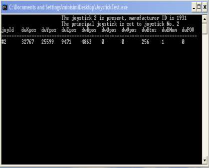
The joysticktest.exe application can be used to observe the behavior of the driver controls. This is very useful in diagnosing a mechanical or electrical problem with a driver input, such as a sticking pedal, or a failing potentiometer, or a loose connection. The executable is located in the miniSim desktop. Launch the application, and a window displaying the values being read by the USB port will be displayed, Figure 24.
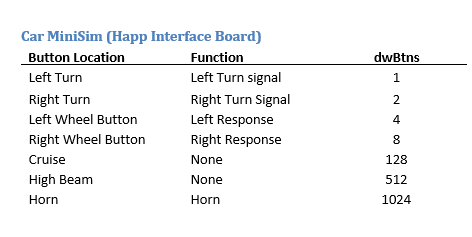
Car MiniSim (Happ Interface Board)
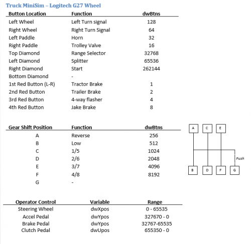
Truck MiniSim – Logitech G27 Wheel
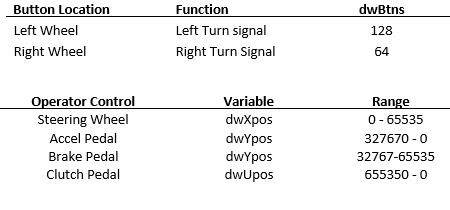
Car MiniSim – Logitech G27 Wheel
For the ECCI Wheel:
JoystickTest-daq.exe
The Joystickdaqtest.exe application is used to view the inputs from other USB data acquisition boards used for driver inputs. The boards that are used are Measurement Computing USB DAQ modules, and the US Digital USB4 board. The systems this applies to are Heavy-Truck MiniSims with a full cab and MiniSims with Adaptive Cruise Control or custom configurations of steering wheel buttons.
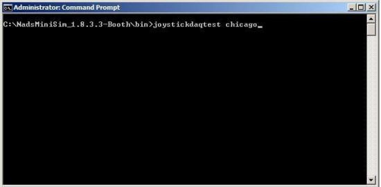
To use, open a command prompt in the Minisim’s bin folder (C:\NadsMiniSim_X.X\bin) and type:
cls <enter>
For systems with the Measurement Computing USB module, type:
Joysticdaqtest Chicago <enter>
For systems with the US Digital USB4 module type:
Joysticdaqtest daq <enter>
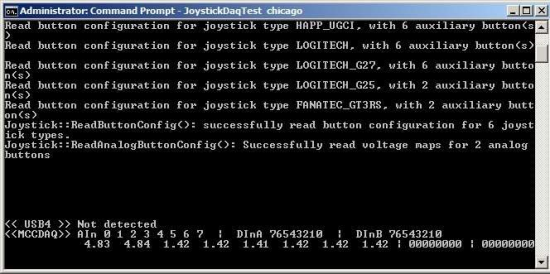
The resulting screen looks like this:
For example, for the Measurement Computing Board, the inputs are as follows:
<<MCCDAQ>> stands for Measurement Computing
AIn 0 1 2 3 4 5 6 7 are the 8 analog inputs, and the analog values are shown below them. In this case, only AIn 0 and Ain 1 are used.
DInA 76543210 and DInB 76543210 are the two arrays of digital inputs and the values (0 or 1) are shown below them.
Note:
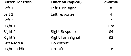
- Button assignments for the Logitech and ECCI wheels are specified in the JoystickButtonsConfig.txt file.
- The ranges for the Operator Controls for the ECCI wheel are specified in the Calibration.ecci_original.txt file.
