Advanced Topic 13
Setup of the Video Capture and Eye Tracking Systems
Note: Review Advanced Topic 11 and 12.
NADS Video Capture System is designed to be integrated into the MiniSim, to capture video of participants drive, and store the video in such a way it can be easily retrieved afterwards.
Using NADS-VidCap
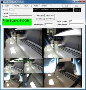
The VidCap system is used in two manners, first when properly installed it is integrated with the MiniSim and will create a new video every time a new drive is started on the MiniSim without any kind of additional user interaction. The second manner the VidCap is used is in standalone mode. This mode does not let the user record a video, but allows for the setup of the capture system. The NADS-VidCap should not be open while launching the MiniSim, the MiniSim will automatically start the VidCap when it’s launched. The video files are saved on the D:\ directory I the vid directory in the appropriate Experiment and Subject Folders. There will be four video files created every time the simulator is run, one for each video input.
Selecting channels
The “VIDCAP” buttons in the top right hand section of the vidcap application select what channels are active, if the button is depressed the channel is on, if it is up, the channel is off. You will also see a “preview” of each active channel, if the channel is active, and you still do not see an image, check your cameras, cabling, and quad split as a video channel may not be properly connected.
Video Format Selector
The video format selector is in the top center of the VidCap program. VidCap supports two video formats MPEG-2 (mpg), and MPEG-4 (mp4). The VidCap program must be restarted for changes in the video format to be made. MPEG-4 produces smaller file sizes than MPEG-2.
Camera Setup
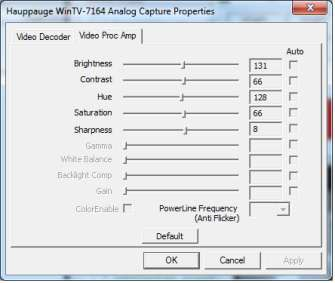
If you click on one of the “Cam X Setup” button in the upper center part of the screen, this will launch the camera configuration window. This window will has two panels, “video decoder”, and “video proc amp”. The “video proc amp” will allow you to set the Hue, Saturation, Contrast and other video settings. Changes here will affect the capture card, and will be saved by the system.
Setting Up NADS-VidCap The VidCap program should be installed on a separate computer with two Hauppauge video capture cards. This machine will need to be connected over a network to the NADS-MiniSim. The MiniSim will have to be setup to communicate with the VidCap.
On the MiniSim Computer:
- located in the C:\NadsMiniSim_X.X\Data directory. The following should be added, or if it is there be sure it is uncommented (remove the leading # symbols):
SUBSYS1 program = videoCap.bat start = 0 period = 1 host = 90.0.0.128 os = windows rshuser = vidcap showconsole = 0 end_subsystem
The 90.0.0.128 line should be replaced with the address of the VidCap machine. This Section will instruct the MiniSim when it starts up to start the VidCap program on the VidCap machine.
NOTE: to disable the vidcap machine, such as when it is desired to run the MiniSim without the vidcap launching, these lines must be commented out by typing a # symbol in front of them. See Advanced Topic 11 – Scheduler Files
- On the MiniSim computer in C:\NadsMiniSim_X.X\bin directory, in the setupenv.cmd file:
set PSLITE_DEST_ADDR=90.0.0.128
The 90.0.0.128 will need to be replaced with the address of the video capture machine.
NOTE: to disable the vidcap machine, such as when it is desired to run the MiniSim without the vidcap launching, the line must be commented out by typing REM in front of it.
On the Video Capture Computer:
On the Video Capture computer in C:\NadsMiniSim_X.X\bin of the VidCap machine, edit the SetupEnv.cmd file:
set MININADSLOCALHOST_IP=90.0.0.128
set PSLITE_DEST_ADDR=90.0.0.1
set PSLITE_DICT_HOST=90.0.0.1
set MININADSMAINHOST=90.0.0.1
The IP address “90.0.0.1” should be replaced with the ip address of the MiniSim computer machine. The IP address “90.0.0.128” should be replaced the ip address of the VideoCap machine.
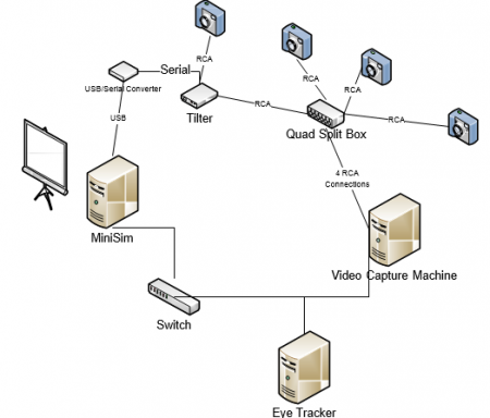
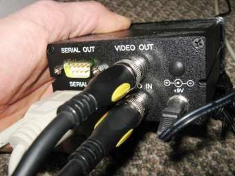
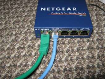
System Connections The following is an overview of the system connections. All the PCs (MiniSim, EyeTracker, and VidCap) are all connected via an Ethernet switch. The serial titler is usually connected to one of the video channels that are routed through the quad-split.
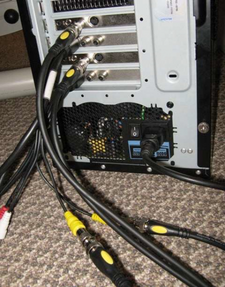
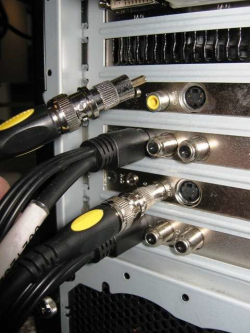
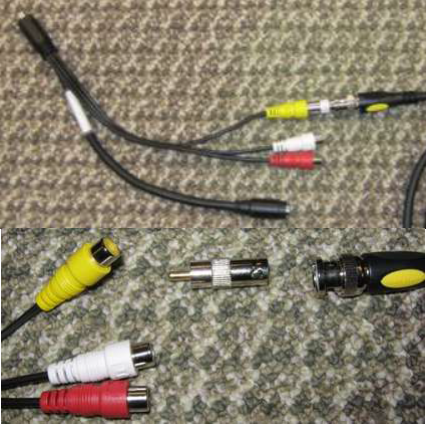
The video connections to the PC are made via the YELLOW RCA jacks as shown in the pictures below. Two of the inputs will be on the Adapter cables, and two will be on the back panel of the PC as shown below. Use the appropriate BNC to RCA adapter to make the connections:
