ISAT User's Guide
Contents
- 1 Introduction
- 2 Scenario Authoring Overview
- 3 ISAT Overview
- 3.1 Installing and Starting ISAT
- 3.2 General Tool Layout
- 3.3 Tool operating modes
- 3.4 Creating New Scenarios
- 3.5 Opening Existing Scenarios
- 3.6 Navigating the Map
- 3.7 Selecting and Editing Scenario Elements
- 3.8 Moving Scenario Elements
- 3.9 Deleting Scenario Elements
- 3.10 Undo
- 3.11 Defining Simulator Initial Conditions
- 3.11.1 Specifying where to start
- 3.11.2 Changing the initial orientation
- 3.11.3 Cab type
- 3.11.4 Motion drive and Settings file
- 3.11.5 BLI Path
- 3.11.6 Other Terrian
- 3.11.7 Motion subsystem scenario
- 3.11.8 Collision Simulation
- 3.11.9 Tire Conditions
- 3.11.10 Brake Conditions
- 3.11.11 Other Vehicle Failures
- 3.12 Working with Components
- 3.13 Emailing Scenarios
- 3.14 Printing the Map
- 3.15 Adding Scenario Comments
- 3.16 Comment Objects
- 4 Defining Common Scenario Element Parameters
- 5 Authoring Deterministic Dynamic Objects
- 6 Behavior
- 7 Authoring Virtual Objects
- 8 Traffic Source
- 9 The Traffic Light Manager
- 10 Triggers
- 10.1 Behavior
- 10.2 Actions
- 10.2.1 Create Element
- 10.2.2 Remove Element
- 10.2.3 Set Button
- 10.2.4 Set Dial
- 10.2.5 Use Traffic Manager
- 10.2.6 Play Audio
- 10.2.7 Vehicle Failure
- 10.2.8 Traffic Light
- 10.2.9 Log Data
- 10.2.10 Terminate Simulation
- 10.2.11 Pre-position Motion Base
- 10.2.12 Tune Motion Base
- 10.2.13 Place Phone Call
- 10.2.14 Start/Stop Data Reduction
- 10.2.15 Set Variable
- 10.2.16 Write Cell
- 10.2.17 Set Visual Display Text
- 10.3 Creating Triggers
- 10.4 Authoring Expression Triggers
- 10.5 Visual Trigger Representation
- 10.6 Using Triggers to build Scenario Events
- 10.7 Verification Tool
- 10.8 Data Reduction Graph
- 10.9 Introduction
- 10.10 Reuse through Copy and Paste
- 10.11 Reuse through Component Merge
- 10.12 Reuse through Groups
- 11 Other Things
- 12 Sample Scenarios
- 13 ISAT Scripting
Introduction
What This Document Contains
This manual is the user's guide for the National Advanced Driving Simulator (NADS) Interactive Scenario Authoring Tool (ISAT), which allows graphical authoring of driving simulator scenarios as well as rehearsal and review of simulator runs. ISAT has been designed to use graphical menus, visual feedback, and guided input dialog boxes to increase usability. This guide describes how to use the ISAT and defines the authoring capabilities of the NADS Scenario Definition and Control (SDC) software.
Audience
This guide was written for an audience that‟s very familiar and comfortable with the use of a Windows based personal computer. It is expected, that readers of this document are familiar with general transportation concepts, high-fidelity driving simulation, immersive virtual environments, and the issues involved in designing scenarios.
Framework
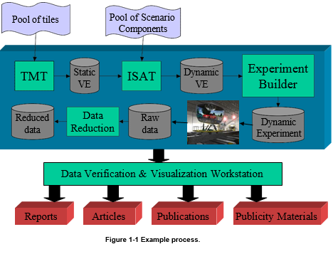
The ISAT is one of a number of tools that can be used to prepare for conducting research studies at the NADS. Therefore, it is important to understand how the ISAT fits within the overall framework. Although it is difficult to pinpoint a process that is simple and easy to comprehend yet covers all potential models of NADS usage, we believe the example provided here covers a significant subset of NADS usage. This example should not be considered a limit on how the NADS can be used to investigate problems. Rather, it is an example that is useful in explaining the role of the ISAT (i.e., the process does not indicate the potential to instrument new cabs or integrate new in-vehicle devices to current NADS cabs, yet these activities are possible). At the same time, not all parts of this process are necessary for each NADS study, and some could be skipped under certain conditions. With those caveats in mind, Figure 1-1 illustrates this process.
The Tile Mosaic Tool (TMT) is a graphical tool that allows the creation of the road network that will be used in the simulator scenarios. The pool of tiles refers to a set of pre-fabricated components, each representing a small geographical area (e.g., a city block or a piece of road) that can be combined by the TMT into a larger virtual environment to be used in the NADS. The output of the TMT is referred to as a static virtual environment because it contains only the physical environment (i.e., the road network, buildings, terrain, and features) but no active elements (i.e., traffic, pedestrians, etc.). The static virtual environment comprises several distinct but correlated databases, each of which is used by the various NADS subsystems while the NADS is running. For example, the visual representation of the virtual environment is displayed by the NADS Image Generator and projectors, whereas the road network information is used by the various driver models populating the virtual environment. The ISAT depends on the existence of a static virtual environment on which to build scenarios. That file is called the LRI (Logical Road Information) file. LRI files typically use the .lri extension. The pool of scenario components represents existing libraries of scenarios that can be used for building new scenarios. The ISAT produces a scenario file, which, in combination with the static virtual environment, represents a dynamic virtual environment. This information is fed to the experiment builder, a tool that allows the specification of the number of participants in a study and the conditions that each participant will be exposed. For example, let us assume that the ISAT produces two scenarios, S1 and S2. If an upcoming study will use eight subjects, then each of the subjects can have any number of exposures using either S1 or S2. The experiment builder allows the specification of such associations. Upon completion of these associations, the cumulative set of files and databases is transferred to the NADS computer systems, where they can be used to execute the runs. After completion, the final output of the simulator is a number of raw data files, which may include video, binary, or other data. These data are then fed to various post-processing tools (this process is referred to as data reduction), and the resultant reduced data can be used by researchers for statistical analysis. Generally, the ultimate goal of this process is the generation of reports, articles, publications, or other publicity materials. This is facilitated through a Data Verification and Visualization Workstation (DVVW), which is a hardware-software custom-developed product that facilitates the integration, understanding, and dissemination of all available information.
Note that no matter how complex the data that is produced in the various phases of the process, the goal of the data-handling tools is to hide this complexity from the user.
Terminology
This section defines terms that are used frequently in this document.
| Visual database | A set of data files representing the physical appearance of a virtual environment. The NADS computers use the OpenFlight format for visual databases. |
| Synthetic environment | A set of correlated databases that fully defines a virtual environment for use in the NADS. |
| Tiles | An instance of a synthetic environment that has been designed so that it can be combined with others, thus allowing the development of larger synthetic environments. |
| Simulator driver | The person driving the NADS. Depending on the context, the term may refer to the actual individual who is driving, or the vehicle representing the driver in the virtual environment. An example of the latter occurs when generating a top-down movie showing what happened during execution. The term simulator driver would be used to refer to the vehicle that shows the subject's actions. |
| Event | A pre-specified set of actions that may or may not involve the simulator driver and are an integral part of a scenario. It is often necessary to have repeatable events. An example of an event is having a car that is waiting at a red light run the light once the simulator driver is ready to enter the intersection. |
| Scenario | A series of events that take place while a subject is driving the simulator. |
| Scenario element | An object that usually is displayed in the ISAT main window, and corresponds to an entity that will exist in the virtual environment during execution of the scenario. |
| Research participant | An individual who drives the NADS during an experiment. Note that a single research participant may drive the NADS several times within the same experiment, and each time they may be exposed to a different scenario. Also called subject. |
| Subject | An individual who drives the NADS during an experiment. Note that a single subject may drive the NADS several times within the same experiment, and each time they may be exposed to a different scenario. Also called research participant. |
| NADS | The National Advanced Driving Simulator. |
| SDM | The Simulator Development Module, a second simulator in the NADS facility that allows testing and tuning of scenarios or other simulator modifications without occupying the NADS. A key feature of the SDM is that it uses hardware identical to or similar to that used in the NADS to ensure compatibility. |
| Coordinator | A coordinator is a scenario component that has no visual representation but can monitor the evolution of the virtual environment and create, delete, or control other entities to orchestrate scenarios. |
| Buttons and dials | In the ISAT, most objects have buttons and dials. When pressed or set, buttons and dials can modify the behavior of the object. Scenario events are often created by coordinators pressing the buttons and dials of objects at key points during the scenario. |
| GUI | A Graphical User Interface is term used to describe a user interface that relies on graphical symbols such buttons, text boxes, and drop down menus, and uses mouse or other pointer device (touch screen, trackball, and joystick). GUI elements refer to individual elements such as buttons. |
In Case of Problems
At the time of this writing, most NADS tools have been tested to meet functional specifications and used extensively in research and studies conducted at the NAD. In the event that you experience any problems or would like to provide feedback, please contact Omar Ahmad at mailto:oahmad@nads-sc.uiowa.edu, or David Heitbrink at mailto:dheitbri@nads-sc.uiowa.edu. When reporting a problem, please provide the following information:
- Your name and affiliation
- The version of the ISAT that you are using (version information is available from the Help/About menu)
- The scenario and LRI that causes the reported problem
- A description of the problem
- A series of steps that need to be performed to recreate the problem
All problems will be addressed in a timely manner in the form of a fix or a workaround.
Document Outline
The remainder of the document is organized into chapters, each covering a particular aspect of ISAT usage. Chapter 2 provides an overview of the issues involved in building scenarios for the NADS and a broad outline of the tools‟ capabilities. Chapter 3 provides an overview of the general graphical user interface features of the ISAT, including how to create new scenarios, save scenarios, navigate the synthetic environment, and so on. Chapters 4 through 9 focus on authoring components, and Chapter 10 is devoted to more advanced subjects.
Scenario Authoring Overview
Basics
Scenario authoring involves the specification of both the static and dynamic elements of a virtual environment so that certain events appear to anyone who drives the simulator under the specific scenario, regardless of small differences in driving style or timing. For example, consider the testing of a new in-vehicle warning device that provides various alarms to warn drivers of potential collisions. The researchers are interested in seeing how different warning signals perform as far as their ability to alert the driver and prevent a collision. To test such a device, one should be able to create potential collision situations. One way to do this is to have the subject drive along a road and through an intersection controlled by traffic lights while the light is green. As the driver nears the intersection, another car (car B), which is initially stopped by the red light on the other leg of the intersection, begins moving, thus blocking the subject‟s path. Let us consider the issues in building such a scenario.
The problem
By far the most critical aspect of such a scenario is timing the motion of car B so that it provides a consistent time-to-collision condition for all subjects, something that is necessary in evaluating the collision avoidance device. However, additional issues have to be considered. When was car B created? Is car B is the same make and model for all subjects, or does it change? How does one ensure that the traffic light is green when the subject approaches as opposed to yellow or red? What if different subjects travel at different speeds toward the intersection?
One approach to building such a scenario is to script everything explicitly that is dynamic about the virtual environment so that its timing is tied to the motion of the simulator driver. For example, time 0 is when the scenario starts, time 40 is when the driver reaches some fixed distance from the intersection, time 60 is when the driver's front bumper enters the intersection, and time 100 is when the driver reaches some point beyond the intersection. Scripting software can determine the value of time based on how fast or how slow the drivers moves and then trigger every change in the virtual environment based on the parametric time scale. For example, the light will turn green at time 20, and car B will begin moving at time 40 and reach the middle of the intersection at time 60. That way, everything is scripted, and no matter how fast or slow the driver moves, the event will happen consistently.
Such techniques are often used in simulators that use relatively short scenarios or involve few dynamic traffic elements. The technique is simple, easy to understand, and provides deterministic results. However, when considering such a technique for use in high-fidelity simulators, several problems arise. In high-fidelity simulators, scenarios are longer and generally involve multiple entities. Coordinating one or two elements through explicit scripting for a 5-minute scenario is reasonable, but coordinating 500 vehicles for a 45-minute scenario is daunting and virtually impossible. Note that the 500 vehicles may not be active at the same time; in fact, they may represent traffic in the opposing lane that is not an integral part of the scenario. Nevertheless, if scripting were the only tool available, it would have to be used for all vehicles. Another complication has to do with what happens after the event takes place. One may want to trigger different scenarios after the near-collision event, depending on the outcome of the first event. For example, if there was a near collision, a less severe event may need to take place at the next intersection, but if the subject veered away early enough, a more severe event may be necessary. Such decision-making cannot be programmed when scripting is the only tool.
An alternative approach is to use intelligent agents that populate the simulator‟s virtual environment and behave autonomously. For example, autonomous driver models can be used to control the various vehicles in the scene. In addition, an intelligent manager can control the traffic lights so their timing follows a specific pattern. Such an approach makes it easy to create scenarios involving multiple entities because the labor-intensive specification of the individual behavior of every entity is eliminated. In addition, the length of the scenario does not overly complicate the development of the scenario because autonomous entities can be created automatically throughout the scenario. However, various other complexities surface. For example, timing and coordination become harder to achieve. Consider the example described earlier. If a traffic light manager controls the state of the traffic lights based on a fixed pattern, there is no guarantee that the light will be green when the simulator driver approaches the intersection. Furthermore, if vehicles are autonomous, there is no guarantee that car B will be waiting at a red light because it may have decided to pick a different route earlier. Even if a car is waiting at the red light, subjects will travel at different speeds. Therefore, they will reach the intersection at different times, and the proper time for car B to block the intersection is not known a priori.
ISAT Toolset Approach
The approach used for scenario authoring in the NADS software and supported by the ISAT is a hybrid between the two techniques, with emphasis on using intelligent agents in conjunction with coordinators to ensure consistency. Specifically, the ISAT allows the user to create any number of entities that behave largely autonomously. In addition, the user can create coordinators; coordinators are "invisible" entities that exist in the virtual environment, but are not displayed. These coordinators orchestrate events by monitoring what happens and modifying the autonomous behavior of the remaining agents to achieve a pre-specified goal. Additional coordinators can be used to automate the generation of traffic, control the traffic lights, modify the environment conditions, and control numerous aspects of the simulator‟s operation. In addition, the ISAT allows the creation of purely scripted entities. The evolution of these entities is completely deterministic, and their timing can be either independent or dependent on the simulator driver's actions.
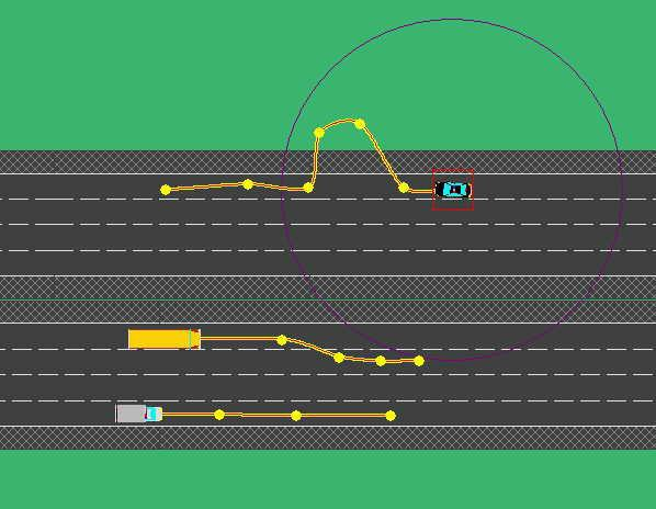
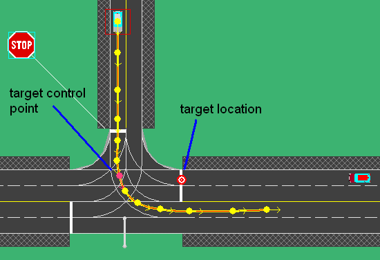
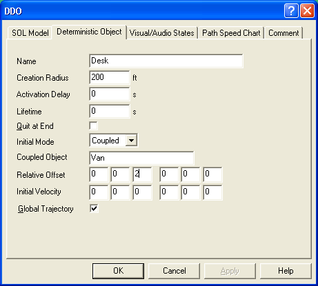
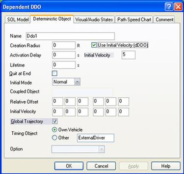
Deterministic objects, or Deterministic Dynamic Objects (DDOs), as they are referred to in the ISAT, are objects whose behavior is pre-scripted by the user. Specifically, the user can select a path and specify the velocity of the DDO at each point in the path. While the scenario is running, a DDO simply follows its path according to the user's specification. Dependent DDOs, or DDDOs, are similar in that they follow a specific path, but their velocity adjusts so they reach a specific point of their path at the same time another entity reaches another target point. DDDOs allow vehicles that follow a scripted path to behave consistently as far as their relative position to another object (including the simulator driver), independent of the variation in the other object's speed. Both DDOs and DDDOs lack collision-avoidance capabilities.
Autonomous Dynamic Objects (ADOs) use a sophisticated autonomous driver model that controls their motion. One can think of an ADO as a human driver that is driving around the virtual environment trying to reach its destination. An ADO will follow the rules of the road, including following the speed limit and respecting traffic lights, and will exhibit most behaviors exhibited by real drivers. A unique feature of the driver model used in the NADS SDC, however, is the ability to have its default behavior modified at runtime. For example, an ADO can be told to follow a specific speed independent of the external conditions, to change lanes, to take a particular turn, and so on. Such commands can be initiated by the researcher while the scenario is running, or can be issued by the various coordinators that can be authored a priori. The latter is by far the most common due to its repeatability. The key coordinators include the trigger, the traffic manager, the traffic source, and the traffic light manager.
The trigger is an entity that is given a series of conditions and a series of actions. It continuously evaluates its conditions and, when they are all true, performs the actions. Examples of conditions include another object reaching a specific point in the road network or a traffic light turning green. Various actions are available, including creating a new entity, deleting an existing entity, modifying the cycle of the traffic lights, terminating the simulation, causing system failures on the vehicle driven by the simulator driver, and issuing behavior modification commands to a set of autonomous entities. A detailed description of how the trigger operates and how the ISAT can be used to specify the trigger‟s events and actions is given later in this document.
The traffic manager is tasked with generating autonomous traffic to populate the area around the driver. Because of a finite limit on the computational resources of the simulator, it is not possible to simulate an arbitrary number of vehicles in real-time. Therefore, traffic is created only in the area around the driver. The traffic manager is given a specific traffic profile and a desired density, and it will create or delete objects as necessary to maintain that density.
A traffic source is another coordinator whose job is to create traffic. Unlike the traffic manager, however, it creates vehicles at a specific point in the database.
The traffic light manager is responsible for controlling the state of traffic lights in the scene. Through the ISAT, the user can program the traffic light manager to achieve just about any timing cycle. In addition, the traffic light manager, in conjunction with the triggers, allows the linking of traffic lights to achieve coordinated traffic light groups.
ISAT Overview
This chapter provides an overview of the capabilities of the ISAT as well as general issues regarding its use. The chapter covers the installing and starting the tool, the overall tool layout, along with the various operating modes supported by the tool. Finally, this chapter covers ISAT tasks that are general purpose in nature, apply to all authoring components, or apply to a scenario as a whole. Subsequent chapters focus on authoring tasks that are associated with specific components such as triggers, or ADOs.
The ISAT utilizes a Graphical User Interface (GUI) that follows the typical GUI conventions of Windows 2000® and later operating systems. ISAT uses a multiple-document interface, where each document represents a scenario. ISAT allows the editing of any number of scenarios at the same time.
Installing and Starting ISAT
The ISAT is distributed on a CD ROM or as a set of install files. In either case, a single Setup program needs to be executed in order to install ISAT. After installation, .bli and .scn files will be associated with the ISAT so double-clicking on such a file will commence the ISAT. In addition, the ISAT icon can be double-clicked to open the tool with nothing loaded. Finally, the ISAT can be started by typing its name on a DOS window, although this requires that the ISAT installation directory be part of the PATH environment variable.
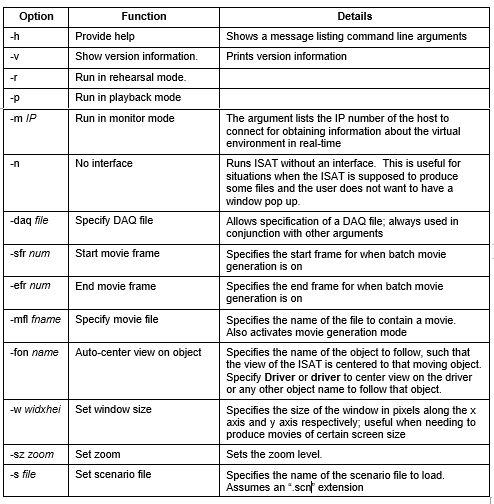
Generally, the only reason to start ISAT from the command line is to run it in Batch mode or to modify some default parameters that cannot be changed once ISAT is loaded. Running the ISAT in batch mode allows the generation of movie animations automatically, without the need for user interaction.
Command Line Arguments
Table X summarizes the ISAT command line arguments. Generally, groups of parameters have to be specified together, whereas other parameters can be specified in isolation.
General Tool Layout
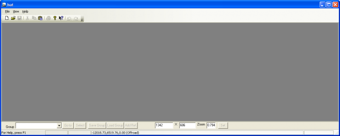
Figure 3-2 illustrates the tool as it appears immediately after invocation.
The ISAT uses toolbars to group similar function buttons close together. If no document is loaded, it displays only a subset of the available menu and toolbar options. The user can either create a new scenario (*.scn) by going to File->New, or open an existing by going to File->Open. When creating a new document the user will be asked for a BLI file, these files contain the “map” and should be located in the “Isat\data\” directory.
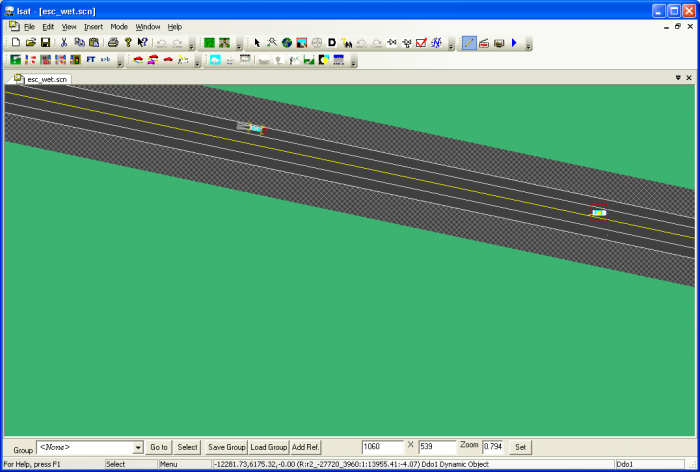
Below Figure 3-3 illustrates how the ISAT looks after a document is loaded.
The tool is conceptually divided into three areas: the top area that hosts the toolbar and menu area, the work area, and the status bar located at the bottom of the window.
Tools, Toolbars, and Menus
The menu bar and toolbars are located at the top of the window. The menu bar used in the ISAT is typical of most Windows programs, such as Microsoft Word. Various toolbars are available immediately below the menu. The ISAT toolbars can be “docked” at different places, including outside the main tool window. Toolbars are organized according to their functions and will be described throughout this document. Toolbars remember their position so if you move them to a specific place, they will be there next time the ISAT is started.
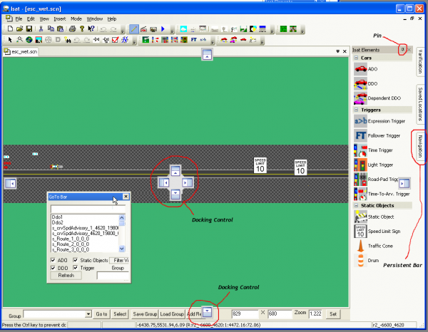
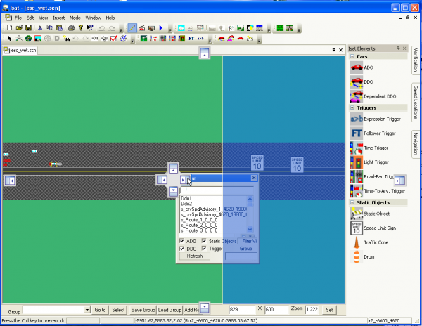
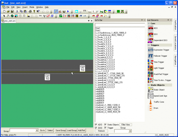
ISAT employs many advance user interface elements that are found in newer Microsoft products such as Visual Studio 2005. ISAT allows for the automatic docking of tools, and embedding tools into each other. Three controls control the docking position a tool, docking control, pin, and persistent bar. When a title bar of a tool is selected, the docking control will appear. If you drag the cursor over to one of the directional buttons, it will dock the bar in said direction. The pin control, located in the upper left hand corner of the control effects how the document is pinned to the interface. If the head of the pin is facing down, the bar will stay visible when not active. If the pin is facing sideways, the control will be added to the persistent bar. When the tool is no longer active it will slide away, and when the cursor is placed over the tool‟s title in the persistent bar, it will slide out again. The pin is toggled from facing sideways or downward by clicking on it.
Work Area
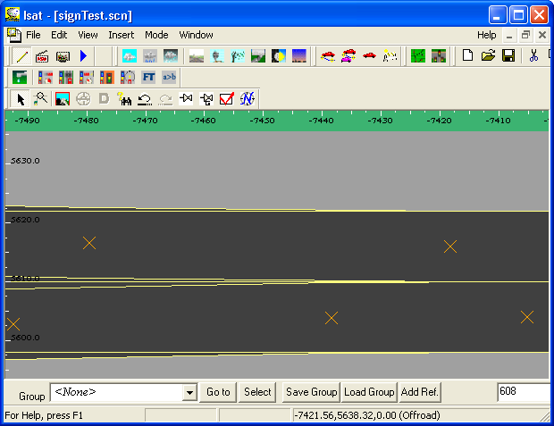
The work area is located below the toolbars and contains a top-down view of the synthetic environment. This view focuses on the features necessary for driving. It displays roads, lanes, lane markings, traffic lights, signs, etc., but does not display forests, buildings, or other visual features that do not affect driving. In addition, certain features are displayed in iconic form rather than in a geometrically correct rendering. For example, an icon is shown in place of signs because an actual rendering of signs from the top would be illegible. Inside the work area, the green color represents areas outside the road network*. Roads are shown in a dark gray color with lane markings in either white or yellow consistent with roadway marking rules. Intersections are shown in a lighter gray color with corridors though them in the same dark gray color as roads. Clicking the mouse button in the work area has different effects, depending on the mode of the tool (see Section3.3).
Status bar
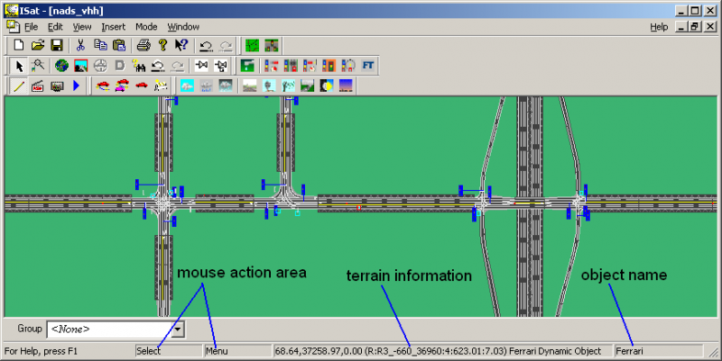
The status bar is at the bottom of the window, and composed of four rectangles that provide a number of changing messages. Figure 3-3 illustrates the various components of the status bar.
The two rectangles on the left side of the toolbar indicate the action that would be performed if the respective mouse buttons were pressed, and the rightmost rectangle contains the name of the object underneath the cursor.
The rectangle immediately to the right of the mouse action area displays information about the terrain underneath the cursor. This information is configurable by the user (see section 3.1.4 for details). When the cursor is over a road, it displays the parametric coordinates of that point in the road network coordinate system. For example, consider the following text appearing on above status bar area:
The first three numbers (68.64, 37258.97, 0.00) are the Cartesian coordinates of the point under the cursor. The (R:R3_-660_36960:4:623.01:7.03) indicates that this coordinate is on a road (the first R), that the name of the road is R3_-660_36960, that the specific lane is lane 4, and that the distance from the beginning of the road along the road centerline is 623.01 units. Lanes are numbered starting with 0 for the rightmost lane when looking along the direction of the road. The distance along the road is 0 at the beginning of the road and reaches the road length at the end of the road. When the cursor is over an intersection, the indicator changes from an R to an I with similar information provided about the intersection. When the cursor is not on a road or an intersection, the status bar will list “Offroad” after the Cartesian coordinates. When cursor is over an object, that object‟s name along with object type is displayed on status bar.
Customizing the ISAT display
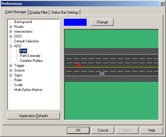
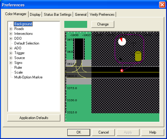
Using the Edit>Preferences menu option brings up the Preferences dialog box shown in Figure XX.
The Color Manager tab allows the user to change the default display settings. The display objects are listed in a two-level hierarchical tree display. Change the color of an object by selecting it from the tree and then clicking the Change button. This brings up a color creation dialog box, which allows selecting of the appropriate color. Once the window is dismissed, the ISAT will re-draw all windows with the new color choices.
The Display Filter tab has two checkboxes. The first is labeled, Always show children. A few of the ISAT elements, such as triggers or sources, involve multiple elements in a parent-child relationship. For example, a source designed to create vehicles at two locations will have two children that act as placeholders, one per location. This setting controls if the children of an element appear always, or only when the parent is selected. Similarly, element labels can be shown all the time or only when an element is selected. The second check box labeled, Show Text Labels, controls this behavior.
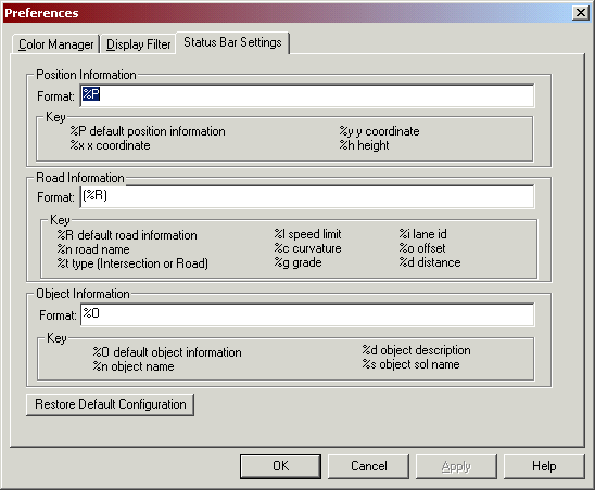
The “Status Bar Settings” tag allows the user to specify the detailed format and information that the ISAT displays about the roads and objects under the cursor. This information is dynamically updated and displayed on the terrain information area of the status bar. The default configuration of the Status Bar Settings tab is shown in
The dialog box displays all available codes that can be used when specified the text to print. Any text that does not use edit codes appears verbatim. For example, assuming that the cursor is at location (50, 50) then using the text “X = %x” in the position text box would cause the following to appear on the status bar: “X = 50”.
Like most ISAT settings all preferences are persistent, i.e., next time the tool is started, all settings will be remembered.
Tool conventions
Whenever possible, the ISAT uses a consistent user interface. Within each mode, the shape of the cursor indicates the type of activity that will take place when mouse buttons are clicked.
The default selection state is indicated by the standard Windows cursor. In that state, the left mouse button is used to select objects and the right mouse button brings up a context-sensitive menu. The left mouse button can be dragged to move elements or to form a rubber band rectangle that selects all objects within it. While authoring various objects that require the user to specify a series of locations, the tool uses the left mouse button to specify a location and the right mouse button to end the selection of locations.
New elements are generally created by first selecting the object category, and then clicking on the location where the object should be placed. A modal dialog box appears to allow specification of additional parameters for the newly created element.
Tool operating modes
The actions that the user can perform while using the ISAT change depending on the tool-operating mode. There are currently four operating modes, each focused on a different phase of the scenario development process. The four modes are authoring, rehearsal, monitoring and replay. The tool first starts in authoring mode. To switch modes, select the appropriate mode from the Mode menu or use the buttons in the mode toolbar:
Authoring mode (Edit Mode)
This is the tool‟s default mode, and is the leftmost button on the Mode toolbar. In this mode, the user can create new scenario elements and modify existing elements. In addition, various key-mouse combinations can be used for navigating around the map. Even though the specific details vary among different scenario elements, creating new and editing existing scenario elements follows a specific patter as described below.
Creating a new scenario element
To create a new scenario element, select the type of element either through the Insert menu or by clicking on the appropriate button in the toolbar. The cursor will change into a vertical arrow:
At that point, clicking on an appropriate location inside the work area will insert the element and pop up a dialog box that allows the user to specify object-specific attributes. Once the parameters have been set to the desired values, pressing OK will insert the element into the scenario. Since each scenario element has its own custom dialog box, the associated options and their meaning are described in the section that focuses on each element.
Editing an existing scenario element
Existing scenario elements can be edited by double-clicking on the element or by right clicking on the element and selecting „Settings‟ on the pop-up menu. Following either of these actions will pop up the object-specific dialog box that allows the user to modify the element‟s attributes. Certain elements that have no visual representation (such as Initial Conditions), these elements can be set from the menu.
Rehearsal mode
The Mode toolbar’s second button is rehearsal mode. It allows execution of the current scenario. A scenario is executed by running on the PC hosting the ISAT the same scenario control software used on the simulator. Even though the software is the same, the evolution of the virtual environment between the simulator and the ISAT will differ because whereas in the simulator there is a human driver that controls the vehicle, when running in the ISAT there is no way to interactively drive another vehicle that represents the driver.
To Rehearse a Scenario
To rehearse a scenario:
- Load the scenario on the ISAT
- Click the rehearsal button on the mode toolbar
- Once the “Scenario Rehearsal” dialog box appears, click on Start
- Double-click on any object to auto-center the map on that object
- Double-click on an empty spot of the map to release auto-center
- Click stop to terminate the simulation
- Click Dismiss to go back to editing mode
Rehearsal Mode Notes
Note that it is possible to use an autonomous driver model to simulate the simulator driver, however, the autonomous driver model “pretending” to be the human driver will operate autonomously, and can only be constrained on its actions by using available authoring tools. So for example, a human driver may drive all over the lane, the ADO simulating the human driver would more likely drive by properly tracking the center of the lane. At the same time, it is possible to force the driver to change lanes by using the lane change dial. In general, having a simulated human driver is better than not having one, but its availability does not eliminate the need for actual testing on the simulator.
To activate the “simulated” human driver, simply define a Start Position and optionally a path (See section 3.11.1) for the ownership. During rehearsal mode, an ADO will be added to the simulation with the same start position as the ownership and the same path as the one assigned to the driver. The simulated human driver will trigger the same triggers as the human driver, and in general will have the same effects as if a human driver is operating the NADS.
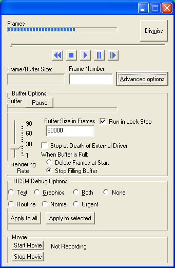
When the Rehearsal mode button is pushed, a command window will appear and after a short period, the dialog shown the figure 3-12 will appear. (NOTE: initially, the dialog box will not show options below the “Advanced” button; press the “Advanced” button to toggle display of the full dialog box).
The rehearsal mode operates by running “frames”. Each frame is produced by running the behaviors and dynamics for a given time period. The data is then stored as a “frame” in the “buffer”. The buffer is a collection of frames, and can be navigated through just like a movie.
The slider above the start button can be used to navigate through the buffer, or by entering the frame number in the “Frame Number” box and hitting Enter. The status bar under Buffer shows how full the buffer currently is. The “Pause” button by the buffer, pauses the operation filling the buffer, this may improve playback quality. The status bar under “Frames” shows how far the playback has progressed in the buffer. Once the “Frames” progress bar is at 100%, the playback may have to wait for more frames to be placed in the buffer.
The “Stop” buttons stops the simulation, and clears the buffer, the “Pause” button pauses the playback. If you want to go back to a frame that has already been deleted in the buffer (see advanced options), you will have to hit Stop, then Start again the rebuild that frame.
Advanced Options
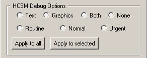
Pressing the “Advanced Options” button exposes additional options that can be used to fine-tune the simulation and how it is rendered. There are two groups of controls; the first group, titled “HCSM Debug Options” modifies how much information is presented by the behaviors during the simulation. The second group titled “HCSM Execution Options” controls the simulation time-step and ISAT rendering rate. Figure 3-13 shows the controls within the “HCSM Debug Options” group.
In general, debugging messages vary between different behavioral models and evolve to meet the need of the developers, but a few items are consistently provided and may be of use to users. It is possible to enable messages for a single behavioral instance (i.e., a single ADO or DDO), or for all elements in the simulation. Debugging messages can be provided as text, graphics or both. Depending on its importance, each message is classified as Routine, Normal or Urgent. To enable messages, first select the appropriate display mode (pick one of the four radio buttons on the top row), then pick which class of messages to display (pick one of the three radio buttons on the second row). Once the modality (text/graphics) and message class is selected, click on “Apply to all” to apply these settings to all current elements, or press “Apply to selected” to apply these settings on the element that is currently selected on the map. One important thing to remember is that these setting are applied when a frame is “run” not displayed. So if the buffer is at frame 2000, and the display is at frame 120 when one of the HCSM options is selected, you will not see the debug information until frame 2000 is displayed. If you select “Run in Lock-Step” this will insure the buffer will be no more than 1 frame ahead of the display.
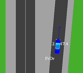
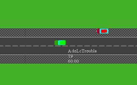
Note that if you pick display of text messages, a new window pops up. That window will list messages as they are generated by the behavioral models. Graphics messages generate additional graphics on the ISAT map during the simulation. For example, Figure 3-15 shows how an ADO appears when graphics debugging has been turned on for that object. A blue arrow provides information on the target point used by the steering controller, and 3 messages appear around the driver showing current speed (in mph, on the upper right), the object id (on the upper left) and the current state used to control the ADO (on the lower left).
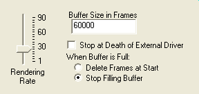
Figure 3-17 shows the “Advanced Options” group. The HCSM Execution Options group allows tuning the ISAT rendering rate. In addition, you can set the buffer size; the buffer is where ISAT stores the data for rehearsal playback. You can set whether ISAT will stop running frames when the buffer is full, by selection “Stop Filling Buffer”, or delete frames that have already been displayed by selected “Delete Frames at Start”. The “Stop at Death of External Driver” flag when selected will stop running rehearsal frames when the external driver has been removed from the simulation. The “Run in Lock-Step” option when enabled will only add frames to the buffer as needed by the display. For example, the rehearsal mode will wait for frame 119 to be displayed before adding frame 120 to the buffer. The rendering rate slider controls the rate at which the playback is shown in frames per second, with 30 being the normal playback speed.
Making a Scenario Rehearsal Movie
To facilitate documentation of scenarios, the ISAT allows making movies of the top down view of a simulation performed in rehearsal mode. To make a movie, there needs to be at least one codec capable of encoding video installed on the computer running the ISAT. A codec is software that “compresses and encodes” video to a data stream. In other words, it stores video data to a hard disk. Microsoft Windows 2000 and XP operating systems come with a few codecs that are appropriate for that task.
There are two methods to make a movie of a session. Both involve some necessary setup, but one method is more automated than the other is.
To make a movie using the automated method:
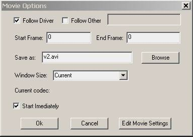
- After getting into rehearsal mode, press the “Start Movie” button on the Scenario rehearsal dialog box – The dialog box shown in Figure 3-14 will appear
- Select the appropriate options as described later.
- Make sure that the check-box titled “Start Immediately” is selected
- Press OK. The Movie Options dialog box will disappear but the simulation will begin. All rendered frames will be saved on the specified file as an AVI movie. Once the predefined number of simulation time steps have finished, movie making as well as the simulation will stop. The ISAT will remain in rehearsal mode.
To make a movie using the manual method:
- After getting into rehearsal mode, press the “Start Movie” button on the Scenario dialog box – The dialog box shown in Figure 3-14 will appear.
- Select the appropriate options as described later.
- Make sure that the check-box titled “Start Immediately” is not selected
- Press OK. The Movie Options dialog box will disappear but nothing happens automatically. From that point on and until the “Stop Movie” button is pressed, all rendering of the ISAT will be accumulated into the file as another frame of a movie. Note that the ISAT renders the top down view for many different reasons: the user zooms in or out, the user changes the panning center, or a simulation time step elapses.
- Press Stop Movie to close the file and complete the movie.
Movie Making Notes
Both the automatic and manual movie-making mode makes use of several common parameters. At the same time, some of the parameters make more sense in automatic mode rather than manual mode.
In automatic mode, it is useful to have the top-down view automatically center on the simulated driver, or on any other object in the simulation. Enable the “Follow Driver” checkmark to auto- center the view on the simulated driver, or enable the “Follow Other” checkmark to activate the adjacent text field into which you can type the name of any of the objects that will act as the auto- center target. In manual mode, this setting is not as important as you can pan manually or select which object to auto center by double-clicking on it.
The name of the AVI file under which a movie is saved can be specified by typing the filename in the text-field titled “Save as:” Press the “Browse” button to select a specific directory or pick an existing file to overwrite.
By default, the size of each video frame is equal to the size of the ISAT window. You can select a different window size by resizing the ISAT window before getting into movie making mode, or by picking a window size from the drop-down menu titled “Window Size”. Note that some codecs have limitations on the size of each video frame. If the ISAT or any of its components crashes consistently when making movies, especially when using codecs that did not come with the OS, experiment with some of the pre-defined window sizes (all of them use multiple-of-8 screen sizes).
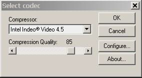
You can select the codec to be used for encoding the video and configure it by Press “Edit Movie Settings” to select the codec. A window similar to the one shown in Figure 3-14 will appear. The “Compressor:” drop down menu will include all available codecs. The “Configure” and “About…” buttons provide codec specific functionality and information. Depending on its capabilities, there may be additional windows that allow for setting the quality, compression ratio and other similar settings. Such windows are codec specific and are not covered here. Typically, there may be additional quick settings available on the “Select codec” window. In the example shown in Figure X, the selected coded (Intel Indeo Video 4.5) allows a single compression quality setting, in addition to other settings selectable after pressing the “Configure…” button.
When in automatic mode, you must type the first and last simulation step that you would like included in the movie in the text fields titled “Start Frame” and “End Frame” respectively. Simulation steps (or frames) are measured starting with 0. For example, to make a movie of the first 20 seconds of a scenario and assuming you have not changed the default simulation time steps, you would type 0 and 600 for the start and end frame respectively.
Monitoring Mode
The monitoring mode is a special mode that can only be used when the computer running the ISAT is within the NADS network. In this mode, the ISAT connects to the simulator’s real-time system, obtains information about the position and state of all visible entities in the virtual environment, and displays them in real time in the ISAT window. In addition, the user can “take control” of a single autonomous entity and control it though issuing certain high-level commands.
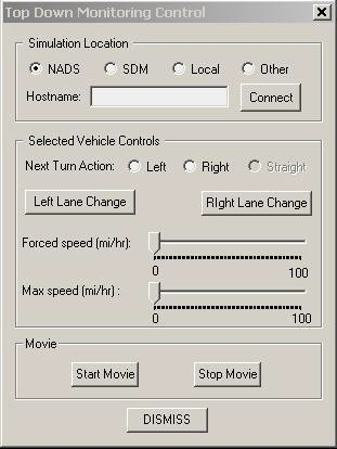
Figure 3-16 illustrates the dialog box that allows control of top down monitoring mode. The “Simulation Location” area allows specification of which simulator’s real-time system the ISAT should connect with. When “Other” is clicked, the user can specify an IP number of host name (assuming DNS is available) for the computer running the real-time scenario software. Once the host has been specified, pressing the “Connect” button initiates the connection. After a short delay, the ISAT will connect or print an error message indicating that it cannot connect.
Once a connection has been achieved, the main map window will display a top down view of the simulator’s virtual environment. The refresh rate may vary depending on the complexity of the map and the number of vehicles in the traffic.
The sub-area titled “Selected Vehicle Controls” is functional when the user has selected one of the vehicles in the virtual environment. It contains a variety of controls that can affect the behavior of the selected traffic element. Note that for these controls to work, the selected element must be an ADO, not a DDO. At the current version, the ISAT cannot tell the user if the selected object is an ADO or a DDO, so the user must be familiar with the scenario before using these controls. Three of these behaviors can be controlled; these are: intersection turning behavior, lane change behavior, and speed selection. Clicking on the radio buttons titled “Left” or “Right” will override the next turn decision that that traffic element has to make. For this to work, the button has to be pressed before the traffic element has committed to the turn; in addition, the turn should be feasible, i.e., the car has to be on the right lane or have enough time to make a lane change. Sometimes, the commit time is surprisingly early making it appear as if the control is not working. The two lane-change buttons operate in a similar manner; they send a command to the element indicating it should make a lane change of the appropriate direction. Finally, there are two speeds that can be set. The max speed limits the naturally occurring maximum speed selected by the traffic element. The traffic element may not reach that speed due to road curvature, other vehicles ahead etc.; however, if possible it will travel as fast as specified in the “Max speed” setting. The forced speed commands to the traffic element to travel at the specified speed, no matter what. The traffic element will ignore curvature, traffic lights, other traffic, and simply go as fast as command. This can cause major problems if abused.
The Movie settings allow recording the evolution of the scenario to a file. See section 3.3.2.2.3 for details on how to specify movie settings.
Playback Mode
The last ISAT mode is the Playback mode. This mode is integrated to provide playback of a simulation that took place on a simulator, provided specific data streams have been collected in a file using the NADS Data acquisition format (NADS DAQ). The NADS and SDM data collection system can be easily configured to collect this data, making it very easy to re-play simulations on the ISAT.
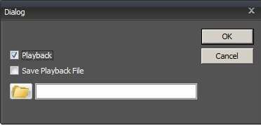
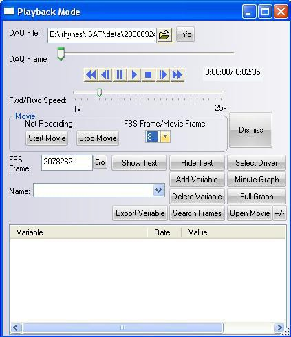
Once the playback mode is selected, a dialog box pops up to allow finer control of mode specific parameters. Figure 3-22 illustrates this dialog box.
The first thing that must be done is selecting the DAQ file to play back. Use the file selection button to bring up a file-selection dialog box. The NADS DAQ files contain data in a binary format that is very efficient for storage but not very efficient for random access. ISAT creates a TOC file for efficiently accessing this data. It may take several minutes to create this TOC file. The TOC file is stored in the same location as the DAQ file, and once created it is used to re-open the DAQ file efficiently. ISAT automatically looks for the TOC file in the same directory as the DAQ file. When copying a DAQ files from a location try to copy over the .toc file, as this will prevent ISAT from having to re-create the DAQ file. If a TOC file does not exist for a given file, and the permission for the directory the file is stored is read-only (such as on a The TOC file replaces the cache system that was used before.
It is important to note that if frames are dropped in the DAQ file some data output may not be 100% correct. Specifically the graph and frame search features may be off slightly due to dropped frames. In addition, any data that should have been collected in the dropped frame would be lost and not available. These errors are not common and in most cases only have minor effects on the accuracy of the data.
Once a file is loaded, the horizontal slide titled “Frame” will show the number of frames available in the DAQ file. The row of buttons immediately below the slider allows VCR-type control of the replay. Seven buttons are provided implementing the following functionality respectively: Play fast backwards, seek back one frame, pause, play, stop, seek forward one frame, and fast forward. In addition to these buttons, the slider itself can be moved around to seek to a specific place in the file. Moving the slider around will cause the main window to display, as fast as it can, the respective frames.
During replay, the Movie buttons can be used to record a movie. Please see section 3.3.2.2.3 on details on recording movies.
During replay, several controls allow fine-tuning the amount of information that is provided to the user. The “Show Text” and “Hide Text” buttons control display of extra labels associated with a selected traffic element. Figure 3-18 shows an example of one traffic element for which text display has been turned on.
In addition to text display, the Playback Mode dialog box displays the current frame as well as the number of traffic elements in the scene. It can also show an ongoing textual display of the values of any other variable that is present in the DAQ file. The value shown for each variable corresponds to the same frame as the animation. To display the value of any of the variables in the DAQ file during the playback do the following:
- Click the drop down menu titled “Names:”. Pick any of the variables you would like to see
- Press the button “Add Variable”
- Next time a new simulation frame is rendered, the value of the variable during that frame will appear in the window at the bottom of the dialog box.
Once a variable is displayed, you can remove it by selecting it in the list box and clicking the “Delete Variable” button.
Search Playback
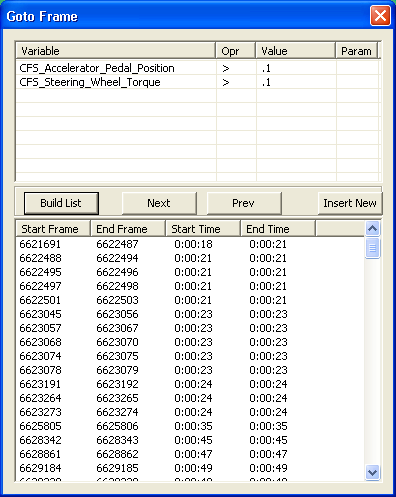
As of version 1.1.31, a new Search feature has been added to the playback. This search feature has been added to allow the searching through the playback for instances for when a given statement is true. Such as Brake Pedal Force > .1, will return all the periods when the brake pedal force what greater than 0.1. This search feature can be accessed by clicking on the “Search Frames” button in Figure 3-22.
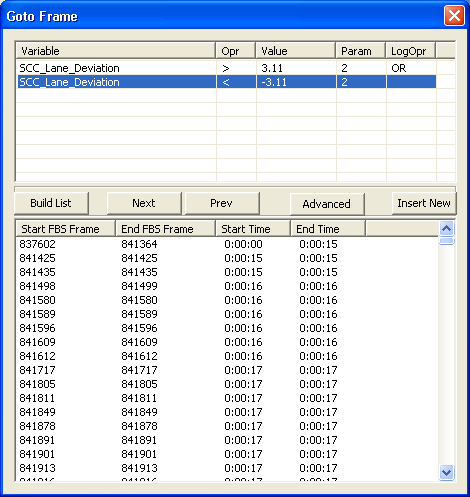
Let’s say we want to find where CFS_Accelerator_Pedal_Position is greater than .1 and the CFS_Steering_Whell_Torque is greater than .1. First, open the "Go to Frame" window by clicking on “Search Frames” as seen in Figure 3-24. From this window, we can build our expressions. Each expression needs 3 things, a Variable, an Operator, and a Value. By Clicking on the cell in the Variable column, it brings up a drop-down where we can select the available variables from the DAQ file. Likewise clicking on the “Opr” column will bring up a drop down where we can select the operator (+, <, >). The value is typed in. The “Param” column takes in the Column number of the variable to use. For instance if we have the variable SCC_LogStream and we want to compare the 3rd value of the variable we would put 3 in the column. If no value is placed in the param column, it is assumed that it is the first value. We can enter multiple expressions, should we run out of available spaces to enter expressions, we can click on the “Insert New” button, and it will insert a new row. The “LogOp” or logical operator column selects the logical operation to be performed between the current row and the next row, if no operation is selected then the AND operation is used. If the row is the last row in the expression then this column is ignore.
Once we have our expressions built, we hit the “Build List” Button. It then finds all there periods where our expressions are true. This can take several minutes depending on the length of the DAQ file. Once the list is built, you can click on the Frame number and it will advance the DAQ playback to that frame number.
We can also produce expressions that are more complex by clicking on the “Advanced” button. This will allow the creation of a text based expressions. The “(“ and “)” are used nesting the expression, each sub expression, such as CFS_Accelerator_Pedal_Position > 0.1 must be enclosed in “(“ and “)”. The following logical operations are allowed between sub-expressions AND, OR, | (or), & (AND). Also the expressions are case sensitive, so the variable CFS_Accelerator_Pedal_Position, must be typed in exactly, for example CFS_Accelerator_Pedal_Position, would not work as it does not match exactly.
Playback Graph
Another new feature that has been introduced in the 1.1.31 release is the Graph feature. This feature allows the graphing of a variable for either the next minute from the current position in the playback or for the entire playback.
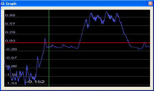
To select the variable that you wish to graph, first select it in the “Name” dropdown in the playback dialog (Figure 3-22). Then to graph the variable hit either the Minute Graph, to graph the variable for the next minute, or Full Graph, to graph the variable for the whole DAQ file. It may take a few minutes to generate the graph. The Minute Graph should take a lot less time to create than the Full Graph. Once done the GL Graph window will come up (Figure 3-25). The green line in the graph is the current position in the DAQ file. The mouse wheel stretches or shrinks the graph along the X- axis (width). Z and X shrinks and expands the graph along the Y-axis (height). The arrow key moves the graphs position, and the “Home” key resets the view back to original view. The value of the variable at the current position in the DAQ file is displayed in the lower left hand corner.
Open Movie
When the Open Movie button is clicked, it brings up an open dialog button to open a movie file related to the current daq file. When the movie file is selected, it will be displayed in a pop-up window. As the daq file is played, it will synchronize the movie with the daq file. The “+/-“ button allows for setting an offset between the current video frame and the daq frame. Since the daq file and the video file will not always start at the same frame, it may become necessary to adjust the start position of the video. In order for this feature to work, your computer must have an mpeg-2 decoder capable of efficiently seeking.
Creating New Scenarios
This section describes how to build a new scenario. It is important to understand that a given scenario is always associated with a specific road network. As a result, the first step in creating a new scenario is selecting the road network on which this scenario will take place. Road networks are stored in files with the extension .bli.
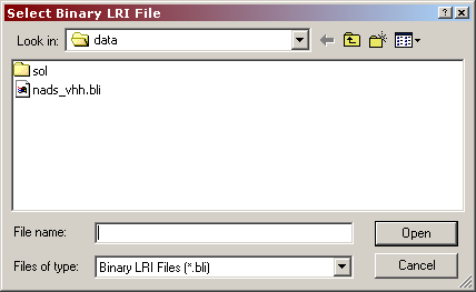
To create a new scenario select the File->New menu option. The dialog box shown in Figure 3-26 appears.
Select the appropriate road network and click on the Open button. After a brief delay (the delay will vary depending on the speed of the computer and the complexity of the selected road map), the road network will appear on the main window of the tool. It is now possible to author scenarios on that map.
Model and Object Pre-creation
During run-time operation, the simulator is very sensitive to processor or memory-intensive operations, including loading objects from the hard drive into memory. The effects of these operations typically exhibit as a momentary pause or 'hang', during which the display no longer updates. The duration of the hang can range from a few frames up to several seconds.
Fortunately it is possible to avoid these types of run-time hangs through "pre-creation". Objects are created by the scenario author at the beginning of each scenario they are required for. Their lifetime can be as short as 1 second; offsetting the creation time by .1-.2 seconds allows the simulator to process the pre-create object list efficiently. The pre-creation process will take a noticeable period of time, so it is necessary to inform the participant not to start driving until told do. On the MiniSim a message text can be displayed for this purpose, and then changed to “Begin driving..” after a pre-determined period of time.
Once an object has been created and then deleted, it is available in memory and the use of the object will not cause a creation hang later in the scenario. For multiple objects that share the same model type, only one pre-creation is needed on the MiniSim. The model will be loaded into memory after one pre-creation and multiple instances of it are created by duplication in memory instead of reading from the hard drive, so there will be no hangs.
Opening Existing Scenarios
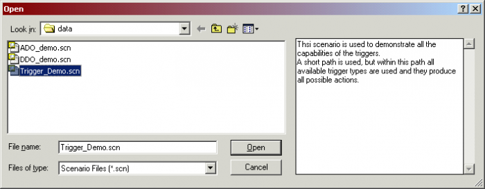
To open an existing scenario, use the industry default File->Open menu option or use the Ctrl-O shortcut key. The dialog box illustrated in
Figure 3-27 appears.
This dialog box is the typical file-selection dialog, with one exception. It provides a text area to the right of the directory listing. Once a scenario file is selected from the file list, the text area on the right shows the comments associated with the scenario.
Clicking on the Open button opens the specified scenario file.
You can zoom in closer to see more details or zoom further out to see a better overview of the map. In addition, the center of the screen can be changed (panned). There are several ways to navigate around the map.
A few navigation shortcuts are available on the navigation toolbar:
The leftmost button ensures that the left mouse button can be used to select elements as opposed to navigation. The second button places the tool in zoom mode. Zoom mode is indicated by the cursor shaped like a magnifying glass:
While in this mode, clicking the left mouse button (or rolling the mouse wheel backwards) on a location of the map makes that location the center of the screen and zooms closer to the scene. Repeatedly clicking on a point of interest can quickly zoom the view to that point. Clicking the right mouse button (or rolling the mouse wheel forward) anywhere in the map display zooms out but does not change the center of the screen.
The third toolbar button zooms and centers the map display so that it covers all scenario elements. This button is useful for quickly focusing on the area of the map where the current scenario is being developed.
The fourth toolbar button zooms and centers the map display so that it covers the entire road network.
The Follow Vehicle is the fifth button on the toolbar. It is only activated during rehearsal or monitoring mode. While in these modes, if the user selects one of the scenario elements in the virtual environment and then clicks on that button, the tool will maintain the same zoom but will pan the view port so that the selected element is always at the center of the screen. This functionality can be achieved also by double mouse click on the scenario element. This mode is useful for tracking a specific traffic element without having to adjust the map display continuously so the element is visible. If more than one element is selected before clicking the button, the view port will keep all of the selected objects in its view, panning or zooming out as necessary.
The sixth button, maintains the same zoom level, but pans the view so that the scenario start position is in the center of the display.
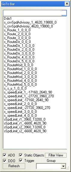
The button with the yellow question mark is used to bring up the find object window (Figure 3-29). Select the object from the list, click OK, and the view will pan putting that object in the center of the view field. The check marks at the bottom of the window filter the list. The refresh buttons refreshes the list and filter the list.
The check mark button brings up the verification tool. This tool checks the triggers for potential errors.
In any of the tool modes, the + and - keys located at the numeric row immediately above the main set of keys can be used to zoom in or out, respectively. Holding the Shift key while pressing + or - increases the amount of zooming performed at each button click.
The four arrow keys can be used to pan around the map. Again, holding the Shift key while pressing any of the arrow keys increases the amount of panning. Note that when clicking a particular arrow key, the map is re-centered as if the viewer has moved in the direction of the arrow key. For example, if the left arrow key is pressed, the map will be redrawn slightly to the left of its original position.
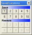
During scenario authoring, it is often useful to go back and forth between specific areas in the database. The ISAT provides the ability to save up to ten different viewpoints in the database and go between them by the click of a single button. To activate this functionality make sure the Saved Locations window is activated. To do so, selected, View->Saved Locations. The window shown in Figure X will appear. It contains two rows of numbered buttons. Buttons on the row titled “Save:” allow making a snapshot of the current view port. Buttons on the row titled “Restore:” allow returning to the respective viewpoint.
Note that initially all buttons on the Restore: row are grayed out, which indicates no viewpoint has been saved for the specific number. Once viewports are saved, the corresponding buttons on the Restore row become active. For example, in Figure 3-25 locations 1, 3 and 4 have memorized viewports.
To save the current viewpoint:
- Ensure the Saved Locations window is visible (click View->Saved Locations) if not.
- Click on any button on the Save: row (note that if the corresponding Restore: button is not grayed out, the previously saved viewport will be overwritten)
To return to a saved viewport:
- Ensure the Saved Locations window is visible (click View->Saved Locations) if not.
- Click on the button on the Restore: row that has the required viewport memorized
A smaller overview window that shows the whole map can be continuously displayed as a way to provide a top view of the whole database. Select menu View->Navigation Window to activate or de-activate display of the navigation window. When the navigation window is visible, a red rectangle within it shows the current boundaries shown in the main ISAT window. Dragging the rectangle in the navigation window dynamically adjusts the viewpoint of the main window allowing quick panning to specific areas in the database.
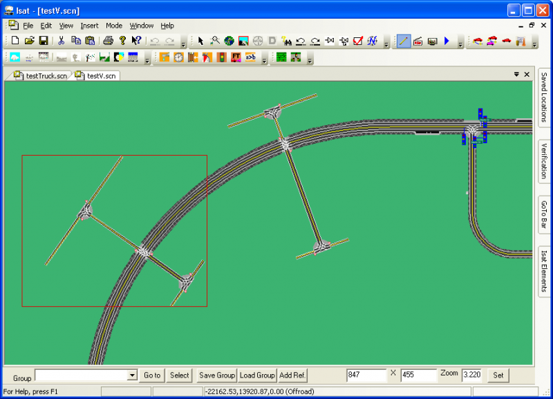
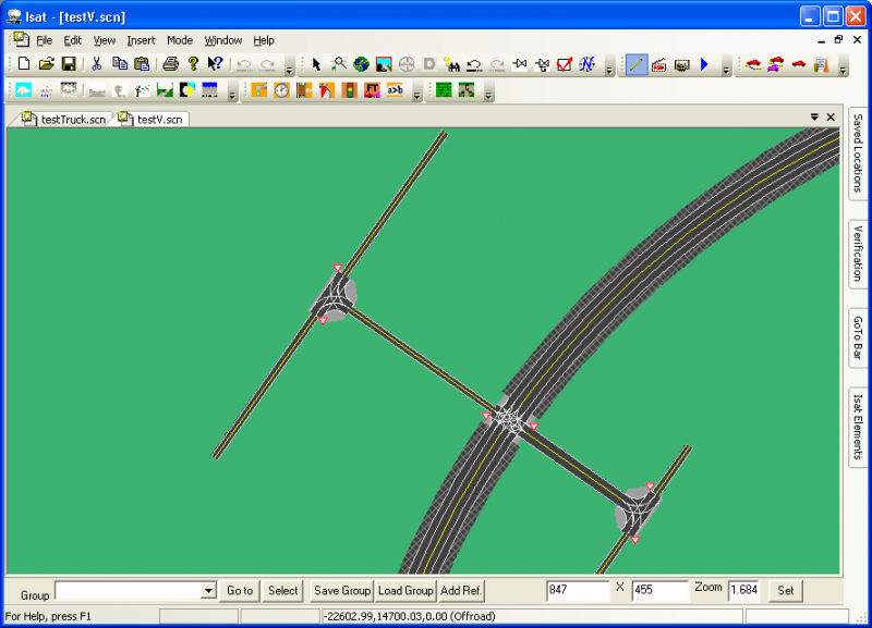
While not in zoom mode, the right mouse button can be used to draw a rubber band rectangle that the tool will automatically use as an area to zoom into. The tool computes a center point and zoom factor so that every part of the rectangle is visible.
For example, consider Figure 3-31. The left side illustrates the rectangle formed by clicking and then dragging the right mouse button, and the right side illustrates how the tool draws the map after the right mouse button is released.
Selecting and Editing Scenario Elements
Selecting elements
In edit mode, scenario elements can be selected either in isolation or in groups. Selection can only take place in the pointer sub-mode (as opposed to zoom mode). To select a scenario element, simply click on it. The selected scenario element will be drawn in a different way to indicate its selection status. In general, a thick red rectangle is drawn around its bounding box. To select more than one element at a time, click on the first element, and then click on additional elements while holding down the Shift key.
Editing elements
To edit a scenario element, double-click on that element, or by right-click on the element and selecting the Settings entry from the pop-up menu. Note that the actual menu will depend on the type of scenario element, but there will always be a Settings entry. After either double-clicking or selecting the Settings option, a modal dialog box reflecting the current settings of the scenario element will appear.
Moving Scenario Elements
Moving a single scenario element
The technique and detailed outcome of moving a scenario element vary somewhat between elements. In general, to move a single scenario element, click on that element and then drag the mouse pointer across the screen. The element will move to follow the pointer. Once the mouse button is released, the element will be placed in the new location.
Note that there is quite a bit of customized behavior associated with different elements. For example, when moving a DDO, only the start position moves, not the whole trajectory. Similarly, when moving an ADO that has a path, the path is modified but not moved. If the ADO is moved to a different road altogether, or if it moved away from the road network, the path is lost. Moving a trigger or traffic source does not move the child elements, just the coordinator. Also, note that individual DDO path nodes can be moved using this technique.
Moving multiple scenario elements
To move multiple elements at the same time, select all of them (see section 3.7.1) and then hold down the Shift key while dragging the mouse pointer. All elements will be moved at the same time. The rules described in Section 3.8.1 still apply. For example, selecting two of the control points on the trajectory of a DDO and then applying a Shift-drag operation will move both control points at the same time.
Deleting Scenario Elements
Scenario elements can be deleted in several ways. You can select the element and hit the Delete key, or by right clicking on the element and selecting the delete option. Finally, you can select the element and then select the Edit->Cut menu option or use the associated shortcut key (usually Ctrl- X).
Undo
The ISAT supports multi-level undo functionality. After performing any action, select the Edit->Undo menu option to undo the most recent operation. Often, the actual label under the Edit menu will indicate the action that would be undone. For example, after issuing a Cut command that deletes a scenario element, the first option in the Edit menu would read Edit->Undo Cut. The Undo command can also be activated though the shortcut Ctrl-Z. Also, the and icons can be used for undo and redo.
Defining Simulator Initial Conditions
One of the first things that must be done when authoring scenarios is defining certain initial conditions that affect both the environment and the simulator driver’s vehicle when the scenario first starts execution. Note that ISAT allows the user to place the start position anywhere, although several limitations exist that ISAT does not enforce. For example, if the initial position is placed away from the road network, the vehicle dynamics will not be able to determine the elevation of the terrain, and the scenario will be interrupted. In addition, it is the ISAT user’s responsibility to place the initial position so that the simulator driver (subject) will not be surprised when the scenario begins (for example, because of an awkward orientation or high-speed heavy traffic nearby).
Specifying where to start
The ISAT allows specification of the simulator driver’s position when the scenario begins. To specify the initial position of the simulator driver, select the Insert->Initial System Conditions->Own Vehicle menu option. After selecting that option, the cursor turns into an insertion pointer:
Clicking the left mouse button inserts a vehicle at the position of the cursor. This vehicle represents the position and orientation of the simulator driver at the beginning of the scenario. Figure 3-33 illustrates the appearance of the vehicle representing the initial position. In addition to specifying the initial position of the simulator driver, the vehicle can act as the human simulator driver while in the rehearsal mode of the ISAT. This is achieved by using an ADO whose start point is the initial position of that vehicle. For all practical purposes (trigger firings, traffic manager, traffic light manager), this ADO acts as the human simulator driver.
Specify a path
A path can be associated with the simulator driver. This path has a dual purpose. First, it can act as a mnemonic for the scenario author of the intended path of the simulator driver though the network. Second, when in rehearsal mode, the path is followed by the ADO simulating the driver. Naturally, when on the actual simulator, nothing can be done to ensure that the actual path taken by the simulator driver is the same as the path specified here.
To specify the path, right-click on the vehicle and select “Extend Path”. The cursor will change into this shape:
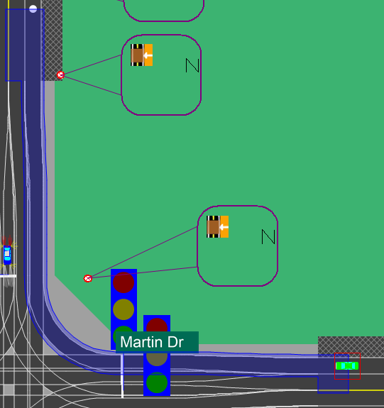
Click on points on the road network to extend the path. To extend the path, click on road locations that an actual vehicle could drive toward from the prior point (or the start of the path) without crossing more than one intersection. Each time a point is clicked, if the location can be connected to from the prior point, a set of blue boxes will outline the route. If there is no access to the new point from the prior point, the path will not be extended. To terminate the path selection, click anywhere with the right mouse button.
Changing the initial orientation
To change the orientation of the initial position right-click on the vehicle representing the start position, and then select the option “Rotate” in the context menu that will appear. After selecting that option, the start vehicle will rotate to follow the cursor. Click any of the mouse buttons when reaching the desired orientation. Note that the actual position does not change, only the orientation does.
Moving the initial position
To change the initial position, click and drag the left mouse button on top of the vehicle representing the start position. The initial position will change to follow the mouse cursor. When the left mouse button is released, the new position of the start vehicle will be set to the current position of the cursor. Note that when moving the initial position, the orientation does not change, but if a path has been specified, it is removed.
Specifying other initial conditions
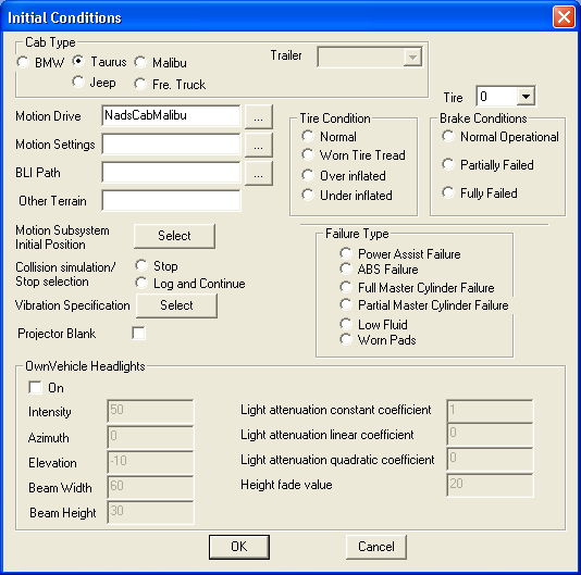
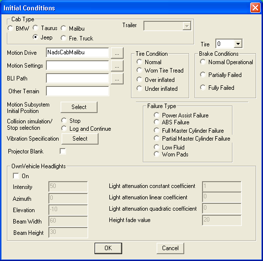
In addition to the placement of the vehicle at the beginning of a scenario, the user can select conditions that affect various aspects of the simulator. All such conditions are collected in a single dialog box. To show this dialog box, select the Insert->Initial Scenario Conditions->Other menu option. The dialog box illustrated in Figure 3-34 appears. The dialog box contains various areas that allow specification of the following types of initial conditions.
Cab type
This selects the cab that the simulation is expected to use. Clearly, selecting this cab in the ISAT does not automatically force the specific cab to appear in the simulator. In fact, switching the physical cab can take as long as eight hours. Instead of a definition, this setting should be considered as a request, either when the scenario is developed by researchers who plan to submit their scenarios to NADS staff, or as a means to document the actual cab used for a particular study.
Motion drive and Settings file
These buttons and associated text-fields allow selection of the file that configures the motion system. This very specialized subject is not applicable unless scenario files are specifically targeted to the NADS, so no additional information is provided here.
BLI Path
If necessary, an alternative path where BLI files are stored can be provided here. By default, BLI files are stored in a directory contained in the NADSSDC_LRI environment variable.
Other Terrian
The NADS software can be configured to utilize a high-resolution low-latency terrain interrogation technique that is overlaid on top of the information contained in the BLI file. When that software is in use, the terrain file is specified here.
Motion subsystem scenario
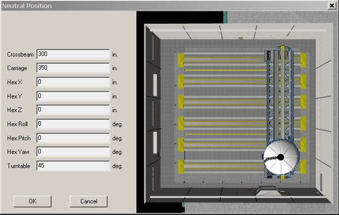
The neutral position of the motion base is in the center of the NADS X-Y track, providing equal amount of travel space for braking or acceleration maneuvers and for left or right lane changes. When the actual maneuver is known a priori, the neutral position can be changed to favor the maneuver. Whereas this setting can be changed dynamically using triggers, it is also possible to define the neutral position at the time that the scenario starts. Pressing the “Select” button adjacent to the “Motion Subsystem Scenario Position” label pops up a dialog box shown in Figure 3-35. The dialog box allows selection of the default neutral position for the motion system. A top down graphic of the simulator dynamically changes to reflect the values typed in the text fields.
Collision Simulation
This setting allows the user to determine what happens when there is a collision between the simulator vehicle and a scenario element or a static object. There are two options. The first option stops the simulator, and the second option simply logs the collision and continues the run. Note that selecting “Log and Continue” does not necessarily include collision information in the DAQ file. The data collection specification must include the collision flag as part of the collected data.
Tire Conditions
The NADS can simulate various tire failure conditions. Specifically, any tire can be made to act as if it has worn tread or as if it were over or under-inflated. This setting specifies the initial conditions for all tires. The tire can be picked by using the drop down menu and the failure condition for that tire is picked by selecting any one of the buttons listed within the “Tire Condition” box.
Brake Conditions
The NADS can simulate various brake failure conditions. Specifically, either overall brake system failures or failures of brake modules on specific wheels can be simulated. This setting specifies the initial conditions of the failure state of the various brake systems and subsystems.
Other Vehicle Failures
This setting controls the initial conditions of various other failure conditions associated with the vehicle driven by the simulator driver.
Working with Components
Components are a mechanism by which scenario elements can be grouped together for re-use.
Emailing Scenarios
To e-mail the current scenario, select the File->Email Scenario menu option. The default e-mail program will appear with an attachment that contains the current scenario.
Printing the Map
To print the map, select the File->Print menu option. In addition, all standard Windows print dialog boxes work as expected, including Print Preview and Print Setup. Note that only the area of the map displayed on the tool’s work area is printed. As a result, be sure to adjust the view port as necessary before invoking the Print menu. If in doubt, use Print Preview to ensure that what will be printed is what is intended.
Adding Scenario Comments
To associate a textual comment with a scenario, select the Edit->Scenario Comment menu option. It is recommended that long descriptive descriptions be added for each scenario to make it easier to remember the goals of a scenario that was built by others. Keep in mind that the scenario comment appears in the preview window when opening an existing scenario file (see Section 3.5 for more details).
Comment Objects
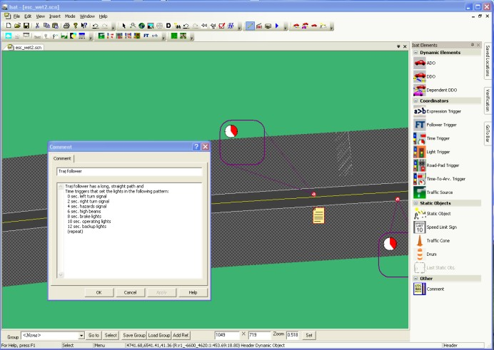
When authoring a scenario it often becomes necessary to create complex events made up of multiple triggers and actions. Because of this, it may not be easy to understand the purpose of a specific group of triggers and other scenario elements when looking at them. It may then be necessary to insert a comment object to describe the goal of a group of scenario elements. This is particularly true if the scenario is likely to be reused in the future. The comment object is denoted by a piece of paper, and is inserted just like any other scenario object. If you double click on the comment object, it brings up a text box. The contents of the text box are stored in the scenario. Scenario objects are only used by ISAT in editing mode, and will not affect anything else.
Defining Common Scenario Element Parameters
For consistency and ease of use, most scenario elements use a similar definition method with a tabbed dialog box where the user can specify the various parameters. These dialog boxes are scenario element-specific; however, they all contain a set of common parameters that have similar functionality, independent of the scenario element. These parameters are defined below.
Name
The name of a scenario element is used to identify that element in the scenario. The ISAT does not force scenario elements to be unique, so it is up to the user to ensure that when a scenario element will be referenced somehow in the simulation, then that name should be unique.
Creation Radius
The creation radius is a threshold in the distance between the scenario element and the position of the simulator driver. At runtime, the element will not be created until the actual distance between the position of the simulator driver and the scenario element is less than or equal to that threshold. For example, consider a scenario element placed at position (0, 0), a creation radius of 300, and an initial position for the simulator driver at location (500, 0). When the scenario begins, the actual distance will be 500, which is larger than 300. Therefore, the scenario element will not be created. What this means in the simulator is that there will be no visible entity at location (0, 0). Furthermore, the computational load on the scenario caused by this element is minimal. Now consider the situation where the simulator driver is driving toward the location (0, 0). The range between the scenario element and the driver is continuously monitored, and when that range gets below 300, the scenario element will be created. In the above example, this will take place when the driver reaches the location (300, 0). The actual effect of the creation varies depending on the nature of the scenario element. For example, if the scenario element has a visual representation (it could be, for example, a stopped vehicle), then this is the time when that vehicle will appear in the simulator’s virtual environment.
The creation radius only affects when a scenario element is created; it does not affect the deletion of a scenario element. In other words, if after creation the range between the driver and a scenario element exceeds the creation radius, the scenario element will not be deleted automatically.
Note that the range between the scenario element and the driver is measured along a straight line, not along the road network. It is the user’s responsibility to ensure that the creation radius is large enough or that the initial position of the scenario element is occluded so that the simulator driver does not observe the creation of the scenario element.
The rationale for having a creation radius is twofold. First, it helps manage the computational load of the system by not creating scenario elements until near the time they will be used. Second, it can be used as a simple authoring mechanism where the rough timing of events is controlled by the motion of the simulator driver.
In the ISAT, a creation radius is shown as a red circle around the element. The default value for the creation radius is 0, which indicates that no such constraint is in effect and the scenario element will be created at the beginning of the scenario.
Activation Delay
The activation delay is the number of seconds between the time a scenario element is created and the time its behavior is engaged. The default value for this parameter is 0, indicating that an element will begin acting as its behavior dictates immediately upon its creation. Note that, upon creation, the visual representation of that element, if any, will appear in the simulator’s virtual environment, even if an activation delay is in effect.
The activation delay is often useful in conjunction with a creation radius. Using a larger than needed creation radius can help minimize the chance that the simulator driver will observe an object popping out of nowhere, and the activation delay can ensure that the object does not begin its activity until the driver is closer. For example, consider a DDO vehicle that is programmed to begin traveling at 50 mph, has a creation radius of 500, and has an activation delay of 3. Once the driver gets within 500 feet of the DDO, the DDO will be created and the vehicle will appear in the virtual environment. However, another 3 seconds have to go by before the DDO will begin moving.
Lifetime
The lifetime is the maximum number of seconds that a scenario element will exist. The time of existence begins when the scenario element is created. Once the lifetime is reached, the element is automatically deleted. Like the other parameters, the lifetime is useful in controlling the computational load of a scenario. Having a finite lifetime ensures that a scenario element does not consume computational resources long after it has performed its task within the scenario.
The default value for the lifetime is 0, which indicates that the maximum lifetime will extend until the end of the scenario (unless, of course, the element is explicitly deleted through other means).
It is the user’s responsibility to ensure that the lifetime, if specified, is large enough to ensure the scenario element is not close enough for the driver to observe its disappearance.
SOL Model
Most scenario elements have a visual representation associated with them. It is important to realize that, in general, the visual representation is decoupled from the behavior of a particular object. Behavior refers to whether the object is a DDO, ADO or static. Visual representation refers to what the object looks like. The visual representation is selected among existing objects contained in the Scenario Object Library (SOL), a library containing numerous objects, their visual representations, and additional properties such as their audio signatures or terrain effects. Objects in the SOL are grouped in categories. Objects in the same category have similar properties and are conceptually similar. For example, all objects of category Truck have a parameter “weight”; however, each object can have its own value for that parameter. At this point, the actual parameters and their values are not visible to the user but are maintained by the SOL internally. See Appendix A for a detailed description of the SOL categories and objects.
The SOL model to be used for all behaviors is selected through a consistent tab in the scenario element’s dialog box. Figure 3-37 illustrates this dialog box tab, as shown within the DDO definition dialog box. There are two components to the dialog box. On the left, a list box contains the SOL categories in a two-level hierarchical tree display. The top level is the category name and the lower level is a listing of the available object types in that category. For example, as shown in Figure 3-37, the category EmergVeh contains two object types named Ambulance and PoliceCar. Clicking on an object highlights the entry and at the same time displays a visual representation of the object on the right side of the dialog box. The selected entry is the one that will be used for the behavior of the object being authored by the dialog box.
Keep in mind that the actual SOL categories appearing on the left side of the dialog box will vary depending on the actual behavior of the enclosing dialog box. Specific SOL categories will be omitted when it makes no sense to associate an object of that category with a behavior. For example, there is an SOL category named "Signs" whose objects are various regulatory signs. This category does not appear in the SOL selection list shown in Figure 3-37, which is used for defining DDOs. Associating a sign object with a DDO would result in a sign that moves about the virtual environment.-
Occasionally, there will be objects that have no convenient visual representation. For example, there is a category named POI which stands for Points of Interest. It includes objects such as audio generators that cause sound effects in the virtual environment but have no visual representation. The picture displayed for such objects is a red X.
The SOL has been designed so it can be extended with additional objects or even additional categories. Adding new objects involves creating entries for the various NADS-correlated databases, such as the visual and audio databases, and rebuilding the NADS software. Although this process is not complicated, it requires access to all the NADS software and intimate knowledge of the software’s structure. Therefore, it is not possible at this time for ISAT users to extend the SOL.
Buttons and Dials
All scenario elements that can be authored by ISAT exhibit some form of behavior when activated in the virtual environment. The complexity of this behavior varies. By far the simplest behavior is associated with the Static Objects. Specifically, they appear and stay put in a fixed location in the database. The ADOs exhibit the most complex behavior through their driver model. To allow orchestration of events within scenarios, the default behavior of the various scenario elements can be changed at runtime. The mechanism used to implement behavior changes is access to buttons and dials. Buttons and dials are conceptual models for inputs associated with each behavior type and operate much like physical push buttons and analog dials everyone is familiar with. Specifically, a button is an input mechanism that when pressed, provides a one-time binary signal to the behavior. Similarly, a dial is an input mechanism that, when set, provides a perpetual analog signal to the behavior. The actual effect of the delivered signal depends on the behavior itself, the state of the scenario element when the signal is received, and the button or dials itself.
For example, consider an imaginary dial associated with the DDO behavior. The name of the dial is Speed. Setting the dial has the effect of changing the speed of the DDO for the remainder of its lifetime. As another example, consider an imaginary button associated with the ADO behavior. The name of the button is TurnLeft. When pressed, this button signals the ADO that it should take the next turn to the left rather than whichever direction it was going to take.
Note that buttons and dials provide a "suggestive" means of control, not an explicit one. This implies that a given behavior may decide to ignore a signal delivered though a button or dial if it cannot gracefully fulfill the request. For example, if the TurnLeft button press came at a time when it was not possible to make a left turn, that request would not be fulfilled. At the same time, if a particular behavior defines that a given button or dial has a direct effect, then the responsibility of reasonable behavior is passed to the user. Again, consider another example of a dial associated with an ADO named ForceVelocity. If this dial is set, the ADO will travel at that velocity, no matter what. However, setting the speed to a fixed value could cause collisions or make the car run off the road.
For each type of behavior that can be authored by the ISAT, this document will provide a listing of all buttons and dials and a description of how they will affect the behavior at runtime. At runtime, the actual pressing of buttons and setting of dials is done though coordinators such as the trigger or, to some limited extent, interactively by the user though the ISAT. The rehearsal mode of the ISAT can then be used to execute the scenario and verify that the runtime behavior is what was expected.
Group Bar
The group bar has many useful features, mostly dealing with groups. A “group” is a group of scenario elements. The go to button cycles through the group members whereas the select button selects all the members of the group.
Groups can be saved to a file, or loaded to a file. To save a group select the group name in the group combo box, and hit the “Save Group” button. This saves the group to a .grp file. This file can be loaded into other scenarios. To load a group from a file hit the “Load Group” button. The Add Ref. button will bring up the external references window. From here, you can add and remove external references. The left hand side of the colon in Figure 3-39 is the scenario name the reference is from, and right hand side is the group name.
The difference between adding a reference, and loading a group from a file, is that the when adding a reference, the group is stored in the original scenario, and cannot be changed in the current scenario. The group members can be changed by making the changes in the original scenario. Loading a group from a file, adds the group to the .SCN file. The elements from the group are just like any other element, and can be changed in the current scenario. Changes to the original group (*.grp) file will not have an effect on the scenario elements that have already been loaded.
Scenario elements can be added to a group by right clicking of them and selecting the group menu, from the context menu. A check will appear next to the group name the element belongs to. The “New Group….” option will allow you create a new group, and add the currently selected element or elements to the new group. Note: you cannot change group membership through use of the group drop-down on the group bar; this is new as of version 1.5.0.
The right most three edit-boxes in Figure 3-38 can be used to set the current screen resolution and zoom level. This is useful for recording movies as it allows the setting of the exact resolution and zoom level. Hit the set button to set the resolution and zoom level to the values specified in the edit-boxes. To change the zoom and not the resolution, leave the two resolution boxes empty (the two boxes on either side of the X) and hit set. Conversely to change the resolution and not the zoom leave the Zoom box empty and hi the set button.
Preferences
ISAT preferences can be set by opening the preferences windows through Edit- >Preferences menu. The preferences window has 5 tabs controlling Colors, Displays, Status Bar, General Settings, and Verify preferences.
The Color manger tab, as it the name suggests is where you can set the display colors for the map. You can set the road color, color of the background and other settings.
The display tab allows you to set some general display options. Currently the only two options in this tab are, Show Exact Roads and Show Control Points. The control points will show up as small X’s on the screen as seen in Figure 3-41. Show exact roads forces ISAT to use an exact representation of the roads instead of a slightly simplified model that it usually uses. This feature as of version 1.1.36 does not work. This may be fixed in future versions.
The status bar settings tab allows you to set the information that is displayed on the bottom of the screen. Information such as x,y coordinates and Speed Limit can be set here.
The General Preferences tab includes two options, Automatically Check ISAT for Updates, and Auto-Save. The Automatically Check for ISAT Updates option when enabled ISAT checks on the local network if a new version of ISAT is available when ISAT is first opened. If a new version is available then ISAT will prompt the user if they want to update to the new version. The Auto-Save options saves a back up copy of the current scenario being edited every 5 minutes. If no changes to the document have been made or the document is not in edit mode then no back up files will be saved. ISAT saves the files as Your-Scenario- Name.SCN.BAK. In order to restore a back up, rename it to your-scenario.scn and open it up in ISAT as usual.
The Verify Preferences tab sets the Verification tool preferences. The Verify at Save option is set, ISAT launches the verification tool at save, if any errors are found the verification window is then displayed.
Authoring Deterministic Dynamic Objects
Behavior
Deterministic Dynamic Objects (DDOs) are objects with no autonomous behavior. These objects follow a pre-scripted path in the virtual environment. There are two types of DDOs: regular and dependent. Regular the user specifies the velocity, whereas dependent DDOs the velocity is controlled relative to the closure rate of another object toward a target point.
The trajectory of a DDO is described by a series of user-specified control points. During scenario execution, the DDO follows a path that visits all control points in order. The exact path is set using a geometric spline to smooth the motion of the DDO between control points. The DDO always starts at the beginning of the trajectory, which must be placed at a point of the virtual environment that contains underlying terrain. All intersections, roads, and the road shoulder including various SOL objects provide terrain information. Control points other than the first one can be placed on points in the virtual environment where there is no terrain. When the DDO crosses from a point with terrain to a point with no terrain, it uses the most recent value from terrain elevation. If the path crosses into an area that provides elevation again, then the DDO will then use the new elevation.
The execution of DDOs is also controlled by the three standard parameters: creation radius, activation delay, and lifetime. These were described in detail in Section 3.17.
The velocity of regular DDOs is explicitly specified by the user at each control point. When traveling along the path, the DDOs velocity will be at the specified value for the control point it is crossing; when it is between two control points, the velocity will be linearly interpolated.
The DDO scenario element is rendered using the actual top down representation of the object in the SOL, and the path of the DDO is shown as a series of points connected by a line. The line uses the same spline interpolation technique that is used by the DDO at runtime, resulting in the display of the same path the DDO will traverse at runtime. When selected, a DDO will be drawn with a red outline. In addition, a circle will be drawn to indicate the activation radius, as in the top DDO shown in.
Dependent DDO Velocity Control
As described earlier, the key difference between a DDO and a DDDO is the method by which their velocity is determined at runtime. The DDO's velocity is explicitly specified at every control point. On a DDDO, however, the speed is controlled by the relative motion of another object in the simulation. To achieve this, a DDDO has three more parameters associated with it. These are the target control point, the controlling object, and the controlling object target location. The target control point is one of the control points on the DDDO trajectory. The DDDO will continuously adapt its velocity so that it arrives on the target control point at the same time that the controlling object arrives at the target location. For example, consider the illustration in Figure 4-2.
The DDDO is shown traveling south on the road controlled by the STOP sign. The highlighted control point is acting as the target control point. The controlling object is traveling from right to left, and its target location is shown with a red striped circle. In this example, the DDDO will adjust its speed so that no matter how fast or how slow the westbound vehicle is traveling, the DDDO will arrive at the target control point at the same time that the vehicle arrives at the target location.
Once the DDDO reaches the target control point, it will continue on its trajectory using the velocity specified at the control points.
Note that the DDDO will never go backwards, including the case where the target location is defined such that the controlling object is traveling away from it. In such a case, the DDO will stop (i.e., the minimum attained velocity will be zero).
DDO Authoring
Creating a DDO
To create a new DDO, select the menu option Insert->Local Scenario Element->Deterministic
Objects->Path Follower or click on the appropriate toolbar icon:
The cursor will turn into the insertion cursor:
Now left click on the map to place the DDO. Once placed the properties dialog will appear. There are four separate tabs in the dialog: SOL Model, Deterministic Object, Visual/Audio States, and Path Speed Chart. The SOL Model tab allows selection of the model to be associated with the DDO. See Section 3.17.5 for more details on the selection of the SOL model. The functionality of the remaining tabs is described below. After setting the parameters click on the OK button, and the DDO will appear on the map. At any time, double-click on the DDO or right-click and select Settings to cause the DDO properties dialog to appear again.
Defining DDO-specific Parameters
The second tab in the dialog box titled “Deterministic Object” contains DDO-specific parameters. Since DDOs have a very simple behavioral model, there is only one parameter in addition to the standard ones described in Section 3.17, namely the Quit at End parameter. This flag specifies what the DDO should do once it reaches the end of its path. If the flag is set, then the DDO will delete itself once it reaches the end of its path; otherwise, it will remain stationary at the last node of its trajectory.
Specifying Visual and Audio States
The third tab, titled Visual/Audio States, allows the specification of non-standard initial conditions for the various visual and audio indicators possible for the specified SOL model. For example, most vehicle models can have their headlights or turn signals operating or can generate sounds such as sounding the horn or, in the case of emergency vehicles, sounding the siren. Since DDOs have no built-in behaviors that will control these effects, the ISAT allows the user to specify the initial visual or audio state of a DDO. Figure 4-45 illustrates the contents of the dialog box tab.
In addition to some typical visual effects that can be associated with various objects, several special effects generally apply only to a small subset of the SOL categories. For example, the Stop Sign that applies to school buses and represents the unfolding Stop sign in the front of the bus. Finally, the Driver Select pull-down menu allows selection of the driver inside the vehicle.
If the selected SOL model does not support any of the choices available in the dialog box, then they would be grayed out.
Visualizng the DDO Velocity Profile
The last tab, titled Path Speed Chart is a read-only dialog box that presents a visual representation of the velocity profile associated with the DDO. The dialog box is useful when trying to verify the velocity that will be followed by the DDO without having to go through each control point one by one. Figure 4-46 illustrates an example of this dialog box.
Specifying the DDO path
Once all necessary parameters have been defined, click on the OK button on the tabbed Deterministic Object dialog box. The dialog box will disappear, and the selected SOL object will appear on the map. At this point, it will have a random orientation and no path will be associated with it. To add a path, right-click on top of the SOL model and select Add Path Nodes on the pop- up menu. The cursor will change into crosshairs:
This indicates that the tool is ready to receive mouse clicks specifying the trajectory. Click the left mouse button to specify the location of the next trajectory control point. Immediately after clicking, the dialog box shown in Figure 4-47 appears.
Type the speed that the DDO should be traveling when crossing the particular control point and hit Enter or click on OK. The system is then ready to receive another control point. After each click of the left mouse button, the dialog box shown in Figure 4-47 will appear. If the speed on all nodes is to be the same, then check the box titled "Use same speed for all following nodes," and the tool will automatically use that speed for the remaining control points without popping up the dialog box after each mouse click.
To end specifying trajectory control points, click the right mouse button. At that point, the DDO is fully specified.
Editing the DDO path
Once the DDO parameters and its trajectory have been specified, it is easy to modify either the velocity associated with each control point or the number and placement of the control points or the orientation of DDO at each control point.
Adding control points at the end of the current path
To add additional points at the end of the trajectory, right-click on the DDO and select the option Add Path Nodes. Then follow the process described in Section 4.2.2 to add control points.
Adding a control point after an existing node
To add a new control point located after an existing control point, place the cursor over the control point after which the new one is to be added, and click the right mouse button. Select the option Insert Node from the pop-up menu. A new node appears halfway between the node that was right- clicked and the next one.
Editing the node velocities
To change the velocity associated with any of the nodes of a DDO, place the cursor over the control point whose velocity is to be modified and click the right mouse button. Select the option Edit Speed. The dialog box shown in Figure 4-48 appears.
Type the new velocity to be associated with this node and hit Enter. This will cause the new velocity to be associated with the selected node, and the dialog box will go away. Instead of hitting Enter, use the buttons titled Previous Node and Next Node to change the selected node and modify its speed without continuously popping the dialog box up and down. To help visualize which control point's speed is modified; click the Center View on the Current Node button to cause the whole scene to be redrawn with the affected node in the center. Click Accept to activate all changes, or Cancel to abandon all changes made to all nodes.
Editing DDO's orientation at each node
The default orientation of DDO is along the direction of the path. To change the orientation of a DDO at any of the nodes, place the cursor over the node and click the right mouse button. Select the option Rotate to change orientation. By selecting Rotate, the arrow associated with the node can be rotated in a circular fashion around the node and can be set to a specific orientation by clicking left mouse button.
Deleting a node
To delete one of the nodes in a DDO trajectory right-click on the node, and then select Delete Node.
DO NOT: Selecting a particular node and hitting delete button on the keyboard would delete the DDO, instead of a particular node.
Dependent DDO Authoring
To create a new dependent DDO (DDDO), select the menu option Insert->Local Scenario Element ->Deterministic Objects->Dependent Path Follower or click on the appropriate toolbar icon:
The cursor will turn into the insertion cursor:
The tool will wait for a single click anywhere on the map. Once the left mouse button is clicked, a dialog box with multiple tabs will appear. There are four separate tabs in the dialog box: SOL Model, Deterministic Object, Visual/Audio States, and Path Speed Chart. The SOL Model tab allows selection of the model to be associated with the dependent DDO. See Section 3.17.5 for more details on the selection of the SOL model. Except for the functionality of Deterministic Object tab, the remaining tabs are similar to normal DDO’s and are described in Section 4.2. Figure 4-49 details various fields in Deterministic Object tab.
Defining Dependent DDO-specific parameters
The second tab in the dialog box titled “Deterministic Object” contains some dependent DDO- specific parameters. When compared with a normal DDO, the dependent DDO differs in only one parameter, namely the Timing Object parameter. Timing Object parameter specifies the controlling object that is tracked by the dependent DDO. As the controlling object moves towards the target point, dependent DDO moves towards target control point as specified in The “Use Initial Velocity” and “Initial Velocity” options specify that you want the DDO to start at a specified speed and to figure out a constant acceleration to use to hit its target on time. If this option is not used it will calculate a constant speed to use. The acceleration and/or velocity are continuously updated, so if the participant speeds up or slows down the DDO will adjust its speed accordingly.
Specifyingthe dependent DDO path
Once all necessary parameters have been defined, click on the OK button on the tabbed Deterministic Object dialog box. The dialog box will disappear, and the selected SOL object will appear on the map. At this point, it will have a random orientation and no path will be associated with it. By clicking on the dependent DDO, a red striped circle (later used as a target location) will appear. To add path, right-click on top of the SOL model and select Add Path Nodes on the pop-up menu. The cursor will change into crosshairs:2
This indicates that the tool is ready to receive mouse clicks specifying the trajectory. Click the left mouse button to specify the location of the next trajectory control point. Immediately after clicking, the dialog box shown in Figure 4-47 appears.
As the speed of the dependent DDO depends on the relative position of controlling object, specifying speed at a particular control point is unnecessary and all it requires is a path built using various control points.
After specifying the path, both target control point and target point have to be authored. By default, the final node at the end of dependent DDO’s path is a red circular point that is target control point. Any node can be made a control point by right clicking the mouse on the node and selecting ‘Set as Target Point’ option; this changes the selected node into a red dot. Target point should be normally placed along the path of Timing Object. Therefore, when the timing object starts moving towards the target point, dependent DDO also starts moving towards the target control point along pre- determined path. As specified earlier, dependent DDO’s are programmed such that they reach target control point at the same time controlling object reaches target point. A more detailed explanation on dependent DDO velocity-control is available in Section 4.1.1
Editing the Dependent DDO Path
Once the dependent DDO parameters and its trajectory have been specified, it is easy to modify either the orientation associated with each control point or the number and placement of the control points.
Adding control point at the end of the current
To add additional points at the end of the trajectory, right-click on the dependent DDO and select the option Add Path Nodes. Then follow the process described in Section 4.3.2 to add control points.
Adding a control point after an existing node
To add a new control point located after an existing control point, right click on the control point then Select the option Insert Node from the pop-up menu. A new node appears halfway between the node that was right-clicked and the next one.
Editing dependent DDO's orientation at each node
The default orientation of DDO is along the direction of the path. To change the orientation of DDO at any of the nodes, place the cursor over the node and click the right mouse button. Select the option Rotate to change orientation. By selecting Rotate, the arrow associated with the node can be rotated in a circular fashion around the node and can be set to a specific orientation by clicking left mouse button. By changing the orientation, a dependent DDO while traversing through the path, would change to specified orientation at that current control point.
Deleting a node
To delete one of the nodes in a dependent DDO trajectory, right-click on the node and select “Delete Node”.
NOT TO DO: Selecting a particular node and hitting delete button on the keyboard would delete the dependent DDO, not the particular node.
Use Initial Velocity
The use initial velocity setting allows you to specify a velocity for the dependent DDO to start with. The dependent DDO will calculate an acceleration value it needs to use so it hits its target position in time. If use initial velocity is not set, the dependent DDO will start at a speed that will allow it to hit the target point in time. In either case, the dependent DDO will adjust either its speed or acceleration continuously based on the target vehicles speed and acceleration to match the closing times on the target points.
Buttons and Dials
The DDOs have the following dials:
| AudioState | This dial allows the dynamic setting of any applicable audio states as shown in Figure 4-45. See the section on authoring triggers for details on how to specify the various settings. Once this dial is set, the DDO will produce the specified sound effects until the end of its lifetime, or until the AudioState dial is set again to a new setting, which could specify no audio effects. |
| Visual State | This dial allows the dynamic setting of any applicable visual states as shown in Figure 4-45. See the section on authoring triggers for details on how to specify the various settings. Once this dial is set, the DDO will exhibit the specified visual effects until the end of its lifetime, or until the VisualState dial is set again to a new setting, which could specify no visual effects. |
Use of DDOs for Building Scenario Events
Because of the low computational cost, DDOs are convenient for manually creating large amounts of ambient traffic when that traffic is not near the driver and is not going to interact with the driver. For example, they can be used as traffic going over a bridge when the simulator driver is driving underneath the bridge, or vice versa. In addition, in certain cases, DDOs can be used for sparse oncoming traffic, especially in divided highways. Since DDOs exhibit no reaction to the simulator driver or other ADOs, it is NOT recommended that they be used among other autonomous traffic elements.
DDOs can also be used for animating pedestrians on sidewalks. By enabling the creation radius parameter, DDOs can "come alive" around building corners just as the driver approaches an intersection. By using the ISAT to fine-tune their timing and trajectories, numerous pedestrians can be added to a scene with minimal effort.
When placing DDOs near the edge of a road or intersection, remember that the DDO “remembers” the most recent elevation when it cannot obtain elevation for the current point. For example, if a DDO starts on a bridge or other elevated feature, and its path extends beyond the road, it will appear as if it is floating in space. It is the user’s responsibility to ensure that such situations do not happen or, if they do happen, they are not visible to the simulator driver.
When authoring DDO trajectories, be aware of using sharp turns, especially with models that are long. Turning about curves with small radius of curvature can look very artificial, especially at high speeds.
Behavior
The ADO behavior is derived from a sophisticated autonomous driver model that exhibits several driving behaviors similar to those exhibited by human drivers. Once an ADO is placed in a scenario, it will travel along a random navigation path in the road network while following all the rules of the road and interacting with other ADOs and the simulator driver. The ADO contains an extensive set of dials and buttons that allows the orchestration of complicated events, despite the highly autonomous nature of its behavior.
The remainder of this section describes ADO behavior in detail. The description is broken down in many sections. First, the overview covers general aspects of ADO’s, and then is followed by sections that focus on specific driving behaviors. Keep in mind that at the time of this writing, the driver model used by the ADO is still evolving through the addition of new behaviors, and the fine- tuning of existing behaviors. As a result, the description focuses on general principles and avoids specific implementation details.
Overview
An ADO can be initialized as a random navigator or given a specific path to follow. When initialized as a random navigator, the ADO builds a path by using its start position as the beginning of a path and then adding intersections and roads. The direction taken when crossing an intersection is selected at random. When initialized with a pre-specified path, the ADO will follow that path and, once it reaches the path's end, it will become a random navigator. In either case, when the term path is used in this section, it refers to the current path of an ADO independent of how this path was defined.
The ADO will use its turn signals as necessary when performing lane changes and turns. In addition, the brake lights will turn on when an ADO decelerates at a rate that would require the use of brakes. At this point ADOs will not use their horns, although they can be forced to produce sound effects through their dials.
An ADO can be associated with various SOL objects, each of which have different physical properties, such as dimension or engine characteristics. In order to provide realistic movement when turning, braking, and accelerating, a multi-body dynamic model is used to simulate the motion of the vehicle. Use of a realistic dynamic model also implies that objects controlled by an ADO cannot have supernatural performance. This is in contrast to DDOs whose speed is computed kinematically, allowing it to achieve any specified performance.
The formalism used for modeling the ADO's behavior is designed to accommodate concurrent implementation of goal seeking. In effect, all behaviors are active at the same time, but only the most important ones are used to guide the vehicle. This allows the ADO to react seamlessly to new circumstances by exhibiting the behaviors as dictated by the current conditions. Currently, the behaviors included in this model include Following, Lane Tracking, Free Drive Speed Control, Lane Change, and Intersection Navigation.
Following
The algorithm currently used by ADOs for following other vehicles is a simple controller that maintains some distance behind a lead vehicle. The actual value of this distance varies between ADOs and can vary from time to time within an ADO through a randomization function utilized to provide variation in traffic. Input parameters can also be used to modify the actual value of the target following distance. In addition, it can be overridden through buttons and dials.
The actual controller responsible for maintaining the distance is tuned aggressively so that vehicles will react quickly when their desired distance is disturbed. This is to ensure that vehicles do not collide with each other or with the simulator driver. However, it is still possible to have collisions if vehicles are forced to change their speed drastically or if their paths are obstructed in a way that makes stopping in time impossible. At the same time, the aggressiveness of the controller often leads to low-frequency oscillations when the speed of a car within traffic changes for whatever reason. To some degree, this oscillation is similar to spring-like oscillations observed in real traffic patterns.
Currently ADOs will not react in any manner to a DDO.
Lane Tracking
The lane tracking behavior is responsible for steering control. The ADO will track the current lane by using a simple steering controller that is tuned to minimize lane incursions during sharp turns. In general, the ADO will track the center of the lane plus or minus a small random perturbation for variability. The controller also attempts to keep the whole vehicle body within the lane boundaries at all times.
Free drive speed control
The speed at which an ADO travels through the network when not following another vehicle is controlled by many factors, including the type of road, the posted speed limit, the road's curvature, and external commands through buttons and dials. In general, if no speed limit is posted, the ADO first computes an estimate of the current speed limit based on the type of road. For example, when on an interstate, a 65-mph speed limit is assumed. If a speed limit sign is passed, the ADO will obey the speed limit and remember it until the next intersection. Finally, the ADO will use the curvature of the road to compute an upper bound on its velocity. The upper bound is computed by calculating the maximum speed around the curve that would expose the vehicle to no more than a threshold lateral acceleration. The actual threshold varies depending on the input parameters, but, in general, it cannot exceed the traction limit of the dynamic model. A typical value is 0.25 Gs.
Once all speeds have been computed (i.e., road default, speed limit, curvature), the smallest is used to guide the vehicle after taking into account the setting of the TargetVelocity dial. Figure 5-51 illustrates the block diagram used for calculating speed control. The illustration is focused on the Free Driving Speed Control logic, but does include the logic used to combine velocity control signals from other behaviors and external inputs.
Lane Change
The ADO looks for opportunities to perform lane change maneuvers. Currently, ADOs change lanes for various reasons. It changes lanes to stay on its path, and it changes lanes to the left if it encounters a slower vehicle in front of it. However, it only changes lanes if slower vehicle’s velocity is less than 90% of the ADO’s velocity. On multi-lane roads, ADOs try to drive in the right lane, although they will change lanes when conditions necessitate traveling in another lane. On a highway, an ADO will change lanes to yield to merging traffic. Finally, an ADO changes lanes due to an external command from the user. This command forces the ADO to change lanes regardless of its current path.
An ADO is relatively intelligent in how it performs lane changes. For example, if an ADO has to turn right at the next intersection and there is a slow moving vehicle in front of it, the ADO will only change lanes to pass if there is enough distance to the intersection to move back into the right lane to make the turn at the intersection. In addition, an appropriate gap must exist between vehicles in the target lane before a lane change maneuver is initiated. The lane change behavior acts dynamically. It continuously re-evaluates the current situation and, if conditions change enough, a lane change maneuver can be aborted.
The intersection navigation logic used by the ADO is designed to accommodate most types of intersections encountered in actual road networks. The general principle used for intersection navigation is to first identify the intersection corridor that will be used to traverse the intersection, then find all vehicles whose corridors intersect the ADO's corridors. Having found the other conflicting vehicles, the ADO uses the rules of the road, including any traffic signs or lights to prioritize all vehicles. At any given time, all vehicles other than the one with the highest priority will stop at the designated hold offset, typically indicated by a solid white line. Once the highest priority vehicle has cleared the part of the corridor that intersects the other corridors, the vehicle that was second in priority becomes the highest priority and proceeds.
It often happens that according to the rules of the road two vehicles have similar priorities, in other words it is not clear which one should go first. When this happens, a random selection is made among the equal-priority vehicles for who will be first. This coordination requires communication between vehicles to ensure that all have a consistent view of who has the right of way. The problem is that given N ADOs trying to negotiate an intersection, this approach requires N2 messages. To avoid this explosion in communication, the intersection navigation logic utilizes a single controller that uses the same decision-making process to explicitly assign priorities to all ADOs. The single controller approach reduces the messages to 2*N, (N messages for the ADOs to communicate their path and another N messages for the controller to send back their priorities), thus minimizing the need for vehicles to communicate with each other. Although this is a centralized approach, the algorithm used still depends on simulating a distributed decision-making typical of real life.
Another challenging complication in intersection navigation is integrating the simulator driver in the traffic. Whereas ADOs can coordinate with each other by declaring their intended path and then obeying the controller's priority assignment, the simulator driver does neither. To address this problem, there is a specialized coordinator, called the Driver Mirror, which is responsible for looking at the simulator driver placement and turn signals and trying to predict the corridor followed by the driver. This information is then communicated to the rest of the ADOs for consideration in their decision-making. As far as priority assignment, because there is no way to tell the driver what to do, the ADOs have explicit logic to deal with the simulator driver. This involves computing the priority of the driver using a similar method as other ADOs, but then acting somewhat different
- When the driver is the highest priority vehicle, ADOs yield to it as usual.
- When the driver has equal priority as other ADOs, the driver always wins the toss.
- When the driver has a lower priority than the other ADOs, the highest priority ADO proceeds as usual.
To ensure that there are no deadlocks (for example, when the ADOs think that the driver is the highest priority, but the driver thinks that another ADO should proceed); the ADOs will use a time- out value for how long to wait. If the time-out expires, the ADOs get new priorities that have the driver at a lower priority level.
To ensure that there are no collisions if the driver decides to move after an ADO has begun crossing the intersection, each ADO uses a forward-looking cone to detect vehicles immediately ahead of it. If the driver appears in that cone, the vehicle stops until the cone area clears.
The intersection navigation logic runs concurrently with other behaviors. If other behaviors dictate a slower speed, then that speed is selected. That way, when multiple vehicles are queued on an intersection, the follow logic of all vehicles but the first would override any intersection navigation commands, thus stopping the vehicle behind the queue leader.
Keep in mind that the intersection navigation logic is continuously being updated to enhance its computation performance and to fix problems that arise when new types of intersections are added to the NADS tiles.
External Commands
During execution, the ADO can be instructed to perform certain actions through buttons and dials. They are listed below along with their definitions.
| ChangeLaneLeft | This parameter causes the ADO to change lanes to the left. The ADO will not change lanes if it is inside an intersection. When this button is pushed, the ADO does not check the lane for gap acceptance. It is up to the user, to guarantee that left lane is clear of traffic. |
| TurnLeft | This parameter causes the ADO to turn to the left-most road at the next intersection. |
| TurnRight | This parameter causes the ADO to turn to the right-most road at the next intersection.. |
| TargetVelocity | If specified, the ADO tries to achieve this velocity whenever possible. The ADO ignores speed limits, but does not ignore road curvatures. |
| ForcedVelocity | If specified, the ADO tries to achieve this velocity as quickly as possible. The ADO ignores speed limits and road curvatures. |
| AudioState | When set, the ADO continuously generates the specified sound(s). The sound will only be audible on the NADS. |
| VisualState | When set, the ADO continuously activates the specified light(s). |
ADO Authoring
The ADO has several initialization parameters that can be set by the user during scenario construction in the ISAT.
The parameters and their resulting behavior are listed below.
| Initial Velocity | If specified, the ADO is created with the specified velocity. Otherwise, the ADO is initialized with a velocity of 0. |
| Target Velocity | If specified, the ADO tries to achieve this velocity whenever possible. |
| Audio State | When set, the ADO continuously generates the specified sound(s). The sound will only be audible on the NADS. |
| Visual State | When set, the ADO continuously activates the specified light(s). |
ADO dials
The following ADO dials have multiple options, and need a little more in depth explanation.
ForcedVelocity
The format of the velocity dial setting has been greatly enhanced, at the same time there is a very big difference between its operation before and after the changes. Whereas before, the dial could be pressed repeatedly, and the new settings would override the previous settings, the current functionality has the dial requiring that once it is pressed, it must be reset explicitly before it can be set again. The dialog in Figure 5-52 can be used to construct the Set Forced Velocity string, it may be necessary to modify the string that it produces. The string provided to the forced velocity dial has the following syntax (any of these styles can be used):
Vel [; Accel] stay
change num [%] [Accel]
sin a b c d
expression
reset
Vel [ [;] AccelToUse]
When using this option, the forced velocity is set to the value specified in Vel. The units are mph. If the optional parameter AccelToUse is specified, the Scenario Vehicle (SV) will reach the new velocity by utilizing an average acceleration as specified in Accel.
Stay
When using this option, the forced velocity of the vehicle becomes the current velocity at the time of the dial press. For example, if the SV is traveling at 57.5 mph and the dial is pressed, then the SV will be forced to maintain that speed.
Expression
The expression option of the forced velocity dial, set the forced velocity based on a expression. The is useful when trying to create a following event in which the lead vehicle has what would seem to the participant a random speed but would be easily described by a relatively simple equation.
The forced velocity dial has its own syntax, that which is described elsewhere. In the example below, expression denotes the dial is a expression forced velocity, “-1” denotes the length of time is infinite for the expression, and the “%” signs denote the beginning and end of the expression.
expression -1 % 60.0 + ( (3.7 * sin( 50 ) ) + ( 1.85 * sin( 11 ) ) ) %
The expression parser used to parse the expression portion of the forced velocity action is the same as used in the expression trigger, except functions are different. The functions used for the forced velocity are for signal generation. The operators function the same as with the expression trigger.
change num[%] [Accel]
This option allows changing the forced velocity of the SV relative to its current velocity. If the percent sign is used, the first parameter (num) is a percent change relative to the current velocity. If the percent sign is not used, then first parameter is the actual change in miles per hour. In both cases, num can be negative or positive. The optional last argument provides the acceleration by which the new speed should be reached and can be positive independent of the sign of the change. For example, if the SV is traveling at 50 mph and the dial setting is "change –10% 2.5" , then the new forced velocity will be 40mph and will be reached at a rate of approximately –2.5 Gs. The setting "change –10% -2.5" would have the identical effect.
Sin a b c d
This option allows specifying a forced velocity that is a function of time according to the formula vel = a + b * sin(c * time + d). Parameters a and b are in mph. The value of time is computed relative to the initial dial press. For example, if the dial press with the setting: "sin 50 10 3.14 0" happened at from 90 (3 seconds from the beginning of the simulation) then the speed at frame 91 would be approximately 50 + 10*(3.14 * 0.016) or about 50 mph.
Reset
This option resets the forced velocity of the SV to nothing, in effect removing the forced velocity constraint. Keep in mind that once a dial is set using any other method (i.e., 'stay', 'change', 'sin' or absolutely), then it must be reset before another setting can be applied.
ADO Properties
In addition to settings dials, ADO behaviors can be set using the properties tabs. The properties for an ADO are set in the same that most other objects are set using a properties dialog. This dialog is brought up when the ADO is initially placed. After ADO is placed it can be accessed by double clicking on the ADO, or right-clicking on the ADO and selecting settings.
ADO Follow Tab
The two ADO Follow tabs are used to set how the ADO follows another scenario element; this could be another ADO or DDO. The TTC Threshold, or Time To Collision Threshold can be used to set how aggressively the ADO fallows. The smaller the numbers are set the more aggressive the ADO is going to behave.
ADO Lane Change Tab
The behavior or ADOs in regards to changing lanes can be set with the Lane Change Tab. These behaviors are the “default” behavior, any “forced lane offset”, or any similar behavior will override these behaviors.
| Turn signal Time | This parameter set how long the ADO will apply the turn signal before turning |
| Urgency | This controls how fast the will try to complete its lane change; lower this value is, the slower it will turn. |
| Steering Force | This controls how fast the can ADO turn its steering wheel during a lane change maneuver, low this number, the slower the ADO will change lanes. |
| Maximum Lateral Offset | The maximum offset effectively control how far the ADO will turn its steering wheel during a lane change. The higher the number here, the faster it can turn. |
| Lane Change due to: | The check boxes here control the reasons why the ADO will choose to perform a lane change. |
ADO Maintain Gap Tab
Behavior
Static objects are used to augment the static features of the scene. They have no behavior other than simply existing in the scene with any of their visual or audio states set to a fixed state. In addition, the scenario system will detect a collision between the simulator driver and any static object inserted by the ISAT. The outcome of that collision depends on the status of the collision effect setting (see Section Error! Reference source not found.).
Static objects impose negligible runtime overhead on the scenario control engine. The overhead on the image generator depends on their visual complexity. In general, it should be possible to insert numerous static objects with minimal effect on performance.
Static Object Authoring
Creating a static object
To create a static object, select the menu option Insert->Local Scenario Elements->Static Relocatable Object, or click on the appropriate toolbar icon:
The cursor will turn into the insertion cursor:
The tool will then wait for a single button click anywhere on the map. Once the left mouse button is clicked, a dialog box with two tabs will appear. The first tab allows specification of the SOL model, and the second tab allows specification of any applicable visual and audio states. These dialog boxes are similar to the respective dialog boxes of other scenario elements.
Once the SOL object has been selected and the visual and audio states of the object have been defined, click on the OK button. The dialog box will disappear, and the top down view of the static object will appear on the map.
Note that even though the ISAT will allow placement of a static object anywhere on the map, unless a road, intersection, or other terrain object is underneath the specified location, a default elevation of zero will be used for placing the object in the scene. If the surrounding scene is at a different height than the static object, it may either appear to be floating above the scene or would be hidden below the terrain.
Rotating or moving s static object
Upon placement, a static object is oriented along the x-axis. To change the object’s orientation right-click on the object, then select the “Rotate” option. At that point, any mouse motion will rotate the object according to the relative position of the cursor. Click any mouse button to leave the object in its current orientation.
To move a static object, click on it and then drag the mouse. The object will move along with the cursor. Release the mouse button to place the object in its new location.
Editing a static object
Double-click on a static object to bring up the “static object definition” dialog box. Change any necessary parameters and click OK. Alternatively, right-click on a static object and pick the Settings menu option.
Deleting a static object
A static object can be deleted in several ways. While the object is selected, click the Del or Delete key, select the Edit->Cut menu option, or use the Ctrl-X shortcut. Another option is to right-click on the object and select the Delete option on the pop-up menu.
Authoring Virtual Objects
Behavior
Virtual Objects are objects that can be placed in the virtual environment, and only have a visual representation. An Icon flashing on the screen would be an example of a “virtual object.” Each virtual object must be given a unique name. There are two different render types for virtual objects, In Scene and Overlay. Overlay objects will not interact with the contents of the virtual environment; these will be displayed with an Orthogonal projection, meaning they will not change size or shape, based on location. In scene objects are inserted into the virtual environment and use a 3D projection, so the farther away they are from the driver the smaller they will be, they can also be obstructed by other objects, such as an oncoming car. Currently, In Scene objects can only be attached to the ownership vehicle. As a part of the virtual environment, In Scene objects can be visually obscured by other objects in the scene.
Authoring Virtual Objects
To create a new Virtual Object, select the menu option and Insert->Virtual Object Or click and drag the Virtual Object from the “Isat Elements” toolbar
The cursor will turn into the insertion cursor:
Now left click on the map where you would like you place your Virtual Object. Once you have placed the Virtual Object, the properties dialog will appear. There are two tabs: Dialog and Comment. The Dialog tab allows you to set all of the properties of the object. By default the name of the Virtual Object is VirtObj, which must be changed to a unique name. The functionality of the remaining fields is described below.
Setting Virtual Object position and size
Setting the position and size of the Virtual Object is dependent on the type of the Virtual Object. Overlay objects use PIXELS as units, and In Scene objects use FEET as units, and angle is always in degrees.
For Overlay Objects, the position is set ( in x,y, ) from the BOTTOM CENTER of the display. Positive X is the number of pixels to the right of the center, Negative X is to the left of the center; Positive Y is the only meaningful Y value here, and it is the number of pixels above the bottom of the display. Width and Height are also set in pixels. Rotation angle is set in degrees, a positive angle rotates the object counterclockwise, and a negative angle rotates the object clockwise
For In Scene Objects, the position is set ( in x, y, z ) relative to the bottom center of the ownership vehicle. The coordinate system is as follows, as viewing from the driver: +x is to the right, +y is forward, and +z is up. The origin of the coordinate system is the BOTTOM center of the ownership vehicle, so if you wanted something to be at eye-level with the driver, you would have to give it a positive z value, as well as a positive y value to bring it out in front of the driver. Units for position and size are in feet, and units for angle are in degrees.
Specifying the stat and using the state table for animation
The bottom half of the Dialog tab is for setting the states of the Object. These states can be used to animate the Virtual Object, or to set a static type object with one state.
The Icon type has different shapes to choose from, as well as an “Icon” option. To use the Icon option, you must enter the filename of the desired Icon in the “Icon Name” field, including the extension; otherwise it can be left blank. To insert a blank frame, you can set “Icon Type” to Icon, and set “Icon Name” to NULL. In the left column there are two numbers separated by a comma, the first number is the state, and the second number is the group. The group number is used to differentiate between animations, and the states are used to differentiate between states within that animation. The group is 1 by default, and a group 0 is reserved for OFF. You can trigger the animation to begin, with a Set Dial->Virtual Object->SetStateIndex action, which is described below. For each state within the group, you can set the Size, Color, and Period. Size is set using the “Width” and “Height” fields. Unlike the same fields above, these “Width” and “Height” fields are scalars of the original size. The period is the duration that the object will remain in that state; the Color has two fields. The Border Color is the color of the border of the shape, and the Fill Color is everything within the border. There is also a Transparency slider for each Color, with 0 being transparent and 1 being completely visible.
Adding Icons
To add an icon to be used as a virtual object, place it in the following directory in your MiniSim install:
\data\Visuals\Models\ModelTx Ex. C:\NadsMiniSim_1.8.3.3\data\Visuals\Models\ModelTx
Triggering Virtual Objects
Virtual Objects can be modified/moved/animated using any of the available triggers. Virtual Objects can be modified by with a Set Dial->Virtual Object-> action
600px|thumb|center|Figure 1-6 Set Virtual Object Dial
Setting Virtual Object Dials
There are seven different dials: SetAnimation, SetRotation, SetPosition, SetColor, SerBorderColor, SetSize, and SetStateIndex.
SetAnimation
This will take in a string and animate the desired Virtual Object according to the string. The format of the input string is as follows :
rotate [degrees per second] ; move [X] [Y] [Z] [rate]
This will rotate the object at the specified rate, as well as move it to the desired position at the specified rate. The movement rate is in units per second, and the object will stop moving once it has reached the specified XYZ. The units and coordinate system are based on the type of Visual Object as described above, with Overlay objects in pixels, and In Scene objects in feet.
SetRotation
Similar to the first part of the SetAnimation dial, SetRotation takes in a string and will rotate the Visual Object at a specified rate. Format is as follows :
rotate [degrees per second]
SetPosition
This will move the Visual Object to the specified position, XY for Overlay objects, XYZ for In scene objects. The units and coordinate system are based on the type of Visual Object as described above.
SetColor
This takes in 4 floats, separated by a semi-colon. The first three floats are the values of Red, Green, and Blue, respectively; The last value is the Alpha, or transparency, value. 1 is transparent, and 0 is completely visible.
SetBorderColor
Similar to SetColor, This takes in 4 floats, separated by a semi-colon. The first three floats are the values of Red, Green, and Blue, respectively; The last value is the Alpha, or transparency, value. 1 is transparent, and 0 is completely visible.
SetSize
This takes in two ints to set the height and width of the object. The units are based on the type of Visual Object as described above.
SetStateIndex
This is used to set the state of the Visual Object, and takes in the group number of an object. The default state for OFF is 0. This can be used to start an animation that you have previously authored in the Dialog tab, in the Object settings as described above.
Traffic Source
Traffic sources are used to create traffic at a specific point. These coordinators are useful for creating ambient traffic. This can save time over inserting a large number of ADOs and DDOs to create this effect manually. This can also be useful for creating traffic at intersections. They can be created by triggers as well. The traffic source is denoted by the icon. A traffic source creates ADOs or DDOs at either a random interval or one that is specified by the user. The traffic source will only create one at a time. The traffic object will be created at the location specified by the user, if traffic source has more then one creation location, the actual location will be determined randomly at runtime.
In order to place a traffic element to be created, click on either the ADO or the DDO button. This will allow you to place either a ADO or DDO in the mini-ISAT view in the dialog. Once placed these scenario element can be moved to any location. They will not exist as regular scenario elements but rather points in which said scenario element might be created by the source at run time. The “Random Uniform” option allows the user to select a random uniform distribution for the time interval between traffic element creations. The min and max edit boxes specify the minimum and maximum time intervals for the random distribution. The periodic option specifies a set of intervals the traffic elements will be created. Such as if 12,3,4 was entered into the periodic edit box, a traffic element would be created at 12 seconds, then 3 seconds latter and then at a 4 second interval after that. The “randomize periodic set” option will randomly shuffle the order the periodic delays. So this option might for create the elements at a interval of 12,4,3, and then at intervals of 3,12,4. Every time a set is run through, it is then reshuffled.
The Traffic Light Manager
Behavior
The Traffic Light Manager (TLM) is responsible for controlling the sequencing of traffic lights in the virtual environment. Note that by default, traffic lights are set to the off state. The TLM must be activated, and timing should be defined for all intersections whose traffic lights need to be operating during the simulation.
Timing is defined for groups of related traffic lights. These groups are called Coordinate Light Groups (CLGs). Currently the grouping of lights into CLGs is done automatically by the software that generates the road network; it cannot be modified by the user. In general, all traffic lights on an intersection are grouped together in a CLG.
Within each CLG, timing is specified by providing an arbitrary number of states and then explicitly specifying the color of each traffic light during that state. The duration of each state is also specified. At runtime, the TLM implements a simple state machine that visits all states in the order they were specified. At each state transition, the TLM modifies the color of the traffic lights in the scene to represent the color specified in the timing table.
In general, the TLM utilizes a small, but not negligible, part of the computing capacity of the scenario computer. However, when the number of traffic lights is very large, the I/O time necessary to communicate the state of each traffic light to the IG can be quite large. As a result, the TLM provides the ability to load balance the system by only operating traffic lights that are within a certain range of the simulator driver. Use of this load balancing is almost mandatory when a scene contains more than approximately one hundred traffic lights.
Defining Traffic Light Timing
Following are the steps for specifying the parameters of the TLM. The TLM can be accessed through Insert->Global Scenario Elements->Coordinators->Traffic Light Manager Menu. Alternatively, click the appropriate toolbar button. A dialog box similar to the one shown in Figure 8-60 appears.
Overview
The dialog box is divided in two major areas: the work area on the left and the view area on the right. The work area is further divided into the authoring area and the manager area. The authoring area allows authoring of the timing table of CLGs, and the manager area allows specification of parameters associated with the TLM.
The following steps are involved in the specification of the traffic light timing tables. First, the intersections whose traffic lights will be controlled are selected. Then, for each of the controlled intersections, the number of states is specified. Finally, the color that each traffic light will have during each state is specified.
Selecting controlled intersections
As described earlier, intersections are used to group traffic lights into CLGs. Thus, in this section, any reference to an intersection is equivalent to a single CLG containing all traffic lights associated with that intersection.
The Applicable Intersections list box contains all intersections in the scene. The actual names are derived though an automated process that does not necessarily yield any useful naming. However, selecting any of the names in the list box will force the view area to center and zoom the display on the selected intersection. For example, the intersection displayed on the view area in Figure 8-60 is named I1_-1320_33660. While an intersection's name is selected on the Applicable Intersections list, clicking on the <- button will move it to the Controlled Intersection list. Similarly, clicking on the ->button will move any selected intersection from the Controlled Intersection list back to the Applicable Intersections list. Only the timing for traffic lights belonging to intersections listed in the Controlled Intersections list can be specified.
Authoring traffic light states
To define the traffic light timing for an intersection appearing in the Controlled Intersection list, first click on the intersection name in that list. Note that the view on the right centers and zooms to the specified intersection. At the same time, the list on the lower part of the Authoring box is updated to reflect all traffic lights in the intersection. Selecting any of the traffic lights in the lower part highlights that traffic light on the view.
The list on the bottom part of the Authoring box initially contains two columns (see Figure 8-60). The left-most column always contains a list of the traffic lights in the selected intersection. Each of the remaining columns to the right represents a state in the timing table. The title of the column indicates the duration of the state in seconds. The contents of that column are the colors of the respective traffic lights while the state represented by the column is active.
To add a new state, click on Add state. A new column will appear in the timing table list. The initial duration of each new state is two seconds, and the color of all traffic lights is set to red.
To change the duration of a state, right-click on the title of the column and select Edit state duration from the pop-up menu. The dialog box shown in Figure 8-61 appears.
Type the desired state duration and click OK or press Enter. The dialog box disappears and the updated state duration appears on the column heading.
To change the color of a traffic light, right-click on the letter representing the color. A pop-up menu containing all possible traffic light colors appears. Select the desired color. Once the pop-up menu disappears, the table will be updated with the new color.
Figure 8-62 shows the timing table list after two states have been defined, in addition to the state that appears by default. The duration of the first state is 2.0 seconds, the duration of the second state is 4.3 seconds, and the duration of the third state is 5.5 seconds. For the duration of the last state, the first light will be green, the second light will be yellow, the third light will be red, and the last light will be flashing yellow.
In the above example, the duration of the whole cycle will be 11.8 seconds. The second traffic light, named signal_r1_-1320_34980_180, will be red for the first two seconds, and then will switch to flashing green for 4.3 seconds; next, it will switch to yellow for 5.5 seconds, and will switch back to red for 2.0 seconds, and so on.
To delete a state, right-click on the heading of the column representing the state to be deleted, and then a pop-up menu should appear, then click Delete state.
Load Management
This section of the Manager Dialog box allows specification of parameters that help balance the I/O load on the host to IG channel, a significant percentage of which can be consumed by continuously transferring the state of hundreds or thousands of traffic lights. In general, there are two ways to reduce the load. The first method is to limit the number of intersections in the Controlled Intersections list to only those that the simulator driver is expected to drive through or near. The second method is by limiting which intersections the TLM will communicate to the IG based on the distance between the simulator driver and the intersection.
When Always on is selected in the Manager section of the dialog box, all intersections in the Controlled Intersections list will be included in the traffic light simulation and communicated to the IG, independent of the distance to the driver. When Near driver is selected, only traffic lights in intersections whose centroid is within the distance specified in the Distance list are simulated and communicated to the IG.
Finally, when "Off" is selected, the TLM is inactive.
Using the TLM in Authoring Scenario Events=
The TLM's involvement in the development of a scenario event can be passive or active. Passive involvement refers to activating the TLM to increase the fidelity of the scenario and the realism of the overall experience, but without having any forced interaction with the traffic lights. Active involvement refers to having the state or state change of one or more traffic lights as an integral part of a scenario event.
Two methods allow synchronization of traffic lights with specific events in the virtual environment. The first method involves the use of a trigger that uses traffic light state changes as a condition for firing. The second method, which applies to all triggers, involves setting the trigger's action to that of forcing a particular traffic light into a specific state (Force_State) within a given amount of time (Force_Time). The first method depends only on monitoring the state of the traffic lights and does not affect the TLM. The second method, however, modifies the operation of the TLM as follows. When a traffic light is forced to a specific state, the TLM computes the time between the current instance and when the traffic light would reach the Force_State. If the calculated time is the same as the Force_Time, then no action takes place. If the calculated time is different than Force_Time, the TLM scales the time step applied to the evolution of all lights in the CLG so that the Force_State will be reached in exactly Force_Time seconds. This approach ensures that the CLG remains consistent, in the sense that two intersecting roads will not both give a green light. For example, consider the timing table shown in Figure 8-62. Let us assume that due to the firing of a trigger, the second traffic light is forced to yellow within one second. For the purposes of this example, let us further assume that the time that the trigger fires, the current time, is one second into the first state. The time between the firing event and the natural arrival of the forced state would have been 5.3 seconds (1 second remaining on the first state and 4.3 on the second state). Because the forced time is set to 1 second, the whole evolution of this state table will be accelerated so that all lights will turn into the colors of state 2 within 0.188 seconds and into the colors of state 3 within 0.811 seconds after switching into state 2. Once the Force_State is reached, the TLM will continue the simulation using normally scaled transitions. One final note regarding timing: Because the overall scenario control system is simulated at a finite time step (currently a 33.3 millisecond time step), any time specification that depends on a resolution higher than the time step is likely to operate in a somewhat random manner.
Triggers
Behavior
Triggers are flexible coordinators that allow the development of simple or complicated scenarios. Simply put, triggers are predicate-action evaluated at runtime. In other words, if condition A is currently true, then perform action B. The predicates dictate conditions that, once satisfied, cause a variety of actions to take place. At runtime, triggers continuously evaluate their predicate conditions and, if satisfied, perform the actions.
There are several types of triggers. Each type is characterized by the conditions that can cause it to fire. Each trigger may then have a number of actions, such as “Create New Element”, “Start Data Reduction”, and so on.
Terminology
Several terms are used to describe concepts associated with triggers. These are described here.
| Firing | Firing refers to performing the actions associated with a trigger. |
| Target Set | The Target Set is a set of scenario elements that the trigger will act upon when it fires. For example, if a trigger is supposed to delete some scenario elements, then the Target Set would include the actual scenario elements that would be deleted. |
| Instigator Set | The Instigator Set is the set of elements whose direct action caused the trigger to fire. For example, if a trigger fires when a vehicle crosses a checkpoint on the road network, the Instigator Set would be the actual scenario element that causes the trigger firing by crossing the checkpoint. |
Uniform Parameters
Although triggers have no visual representation in the virtual environment (i.e., the simulator driver has no visible indicator that triggers exist), they are placed in fixed locations. Associating a location with a trigger allows use of the standard scenario element parameter Activation Radius.
Furthermore, all triggers have an Activation Delay and Lifetime parameter. For a detailed description of these parameters, see Section 3.17.
In addition to these scenario element global parameters, all trigger types share additional input parameters as follows.
One Shot
This is a binary input parameter. If set, the trigger will delete itself after firing once. If not set, the trigger will remain in the simulation after firing. The default value for this parameter is cleared.
Fire Delay
This parameter specifies the interval between the time when all conditions are satisfied and the time when the trigger fires. The default value of this parameter is 0, meaning that firing will happen immediately after the conditions are satisfied.
Denounce
This parameter specifies the minimum time that must elapse between successive firings of the same trigger. This parameter is useful for triggers whose conditions remain true continuously after some point in the simulation. In such a case, a trigger would fire continuously (i.e., once at each iteration of the scenario control software), which may or may not be desirable. The default value for this parameter is 0, indicating that as long as the conditions are satisfied; a trigger will fire once per iteration.
Priority
The priority setting controls the order the triggers are evaluated in. A high priority trigger would be evaluated before a low priority trigger. This is useful when there is interdependence between triggers. For example if you have a road pad trigger that sets a variable called “FireAlertSystem”, and you had an expression trigger that looked for the condition where “FireAlertSystem” was greater than 0. If the road pad trigger is set to a “high” priority, and the expression trigger is set to a low priority we can guarantee that the expression trigger will fire in the same frame as when the road pad trigger fires.
Actions
Once a trigger fires, it performs one or more actions. The possible actions are independent of the trigger type. The following actions are defined, along with action-specific parameters.
Create Element
This parameter creates a new scenario element. The new scenario element can be an ADO, DDO, environment condition, or a traffic source.
Remove Element
This parameter removes scenario elements from the scenario. The actual elements to remove (the Target Set) are specified though another set of parameters as follows:
| Name | This is a set of names; any element whose name matches any name in the set is deleted. |
| Type | This is a set of SOL types; any element whose type matches any type included in the set is deleted. |
| Geometric Position | This is a circular region; any element in that region is deleted. |
| Instigator Set | This parameter is Boolean. If set, it indicates that the trigger will delete the elements that caused the trigger to fire. See Section 10.1.1 for a more detailed description of the Instigator Set. |
Set Button
This action presses the button of an element in the scenario. See the individual descriptions of scenario elements for details on the actual effects of pressing their buttons. The Target Set is specified the same way as in Remove Element.
Set Dial
This action sets the dial of an element in the scenario. Such as, you can select a vehicle failure, that which will cause the participant’s vehicle to fail in some manner during the drive, or a “Lane Change” to cause a ADO to change lanes. See the individual descriptions of scenario elements for details on the actual effects of setting their dials. The Target Set, is the set that is effected by the dial, it is specified the same way as in Remove Element.
The define parameters button brings up a dialog to define to help build the dial string. This string may have to be manually modified by the user. Some actions may have additional dialog to help build more complex dial strings such as the forced velocity dialog (Figure 5-52).
Use Traffic Manager
This action forces the traffic manager to use a different Traffic Manager Input Sets (TMIS). See Error! Reference source not found. For details on how to define TMIS.
The sole parameter associated with this action is the name of the TMIS.
Play Audio
This action causes a specific sound to be played in the simulator audio system. The sole parameter associated with this action is the identifier of the audio message.
Vehicle Failure
This action causes a failure on the simulator vehicle. The following types of failures can be programmed:
| Tire blowout | A tire blowout forces any of the tires to fail. A failure can be
instantaneous or gradual. If gradual, the amount of time it takes for the tire to go flat can be specified. |
| Brake failure | A brake failure forces the brake system to fail. When specific tires are involved in the failure, the actual tire can be specified and the severity of the failure can also be specified. The following failure modes are supported:
|
| Alert conditions | These are various alerts corresponding to various lights in the dashboard. The following are the corresponding alert conditions:
|
| Speedometer failure | In a speedometer failure, the speedometer shows incorrect speed but still a linear function of actual speed. A percentage is specified as the error factor. |
| Tachometer failure | This operates the same as speedometer failure, but affects the RPM indicator. |
| Cab Components | Failures can be triggered for the various cab components as follows:
|
Traffic Light
This action causes a particular traffic light to go into a specific state within a given amount of time. Both the traffic light and time are specified. Note that forcing a specific traffic light to a new state will change the timing of the overall intersection. See Chapter 9 for more details on how forcing traffic lights to new states affects the TLM.
Log Data
This action writes a value to a logstream. The logstreams will be readable in the DAQ file after a scenario has been run, and is useful to denote certain events in scenario. For instance, it may be useful to denote when the driver is 500 feet from an intersection.
Terminate Simulation
This action causes the overall simulation to terminate.
Pre-position Motion Base
This action causes the motion base of the NADS to select a new neutral point. The actual neutral point is specified though the actuator displacements. The idea behind this action is to move the motion in a location that allows better performance when the upcoming maneuver is known.
Tune Motion Base
This action selects a new set of tuning parameters for the motion system. Different tuning parameters provide better response on different road types. For example, a tuning file may work best for highway driving but perform poorly on city streets. This action allows selection of the tuning parameters at runtime.
Place Phone Call
This action causes the system to place a phone call. This action was developed specifically to support driver distraction work, in that it provides a deterministic method for initiating phone calls that have to be answered by the simulator driver. The actual implementation of this action requires cooperation with additional hardware and software installed at the NADS.
Start/Stop Data Reduction
The start and stop data reduction are one of the more important trigger actions, they instruct the simulation to either start a data reduction or stop a data reduction. A data reduction is used to produce data about an “event”, such as a driver being cut off, or an object falling of the back of a truck. For example, if a vehicle in front of a participant suddenly brakes and the user is boxed in from the side by another vehicle such that the participant cannot change lanes. In this instance, we would want to know how long it takes participant to apply the brakes from first seeing the vehicle make a sudden stop. We can do this by first inserting a trigger to fire a “start data reduction” action when the car in front of the participant’s vehicle stops, and then inserting a trigger with a “stop data reduction” to fire when the participant steps on the brake pedal. This will later produce data describing how long it took the driver to react to the event.
Start and stop data reductions produce embedded data reduction items. The advantage with embedded data reductions items is that they will automatically produce reduction data reports after the data is in the post-processing phase. Embedded data reduction saves time over other data reduction techniques
Each data reduction is identified by its group number, its variable, and its column name. Each data reduction must have at least one “start data reduction” action, and one “stop data reduction” action. Each data reduction may have multi “start data reduction” actions, and multiple “stop data reduction” actions.
The data reduction variable describes the type of data reduction to be performed, the group number is used when more than instance of a type of variable is used, then group number can be set to differentiate between the two data reductions. The column name is used to describe the data reduction. Figure 9-64 describes the data reduction variables.
When a start or stop data reduction action has been selected, hit the “params” button to select the settings for the stop and start data reduction. When inserting a “stop data reduction” action, you will have a choice of selecting the variable, and the group. By double clicking the variable type it will select the variable type and bring up the define parameters dialog (Figure 9-66). Here you can specify the column name, that which should be unique for the group. Multiple starts can have the same column name as long as they also have the same variable name as well; in essence, they are the same start data reduction. It will often be necessary to start a data reduction at multiple points.
The stop data reduction is slightly different from the start data reduction. When the “params” button is hit, it brings up a list of start data reductions. Start data reductions with checks by them have already been paired with a stop. It is ok to select a stop data reduction that already has a stop selected. The data reduction can be set by either then double clicking on the variable name, or by double clicking on one of the start data reductions. This will bring up the set parameters dialog; this is the same as the start data reduction except the column name can only be selected from a drop down list. By clicking on "start data reduction" it will bring up the parameters dialog with the start data reductions column name already selected and the group number will be switched to match the start data reductions group number. Multiple stops can be selected for the action, but they all must have the same group number.
Set Variable
The set variable action set a given variable to a given value. This can be used to reset a variable that is used as a counter between simulation runs.
Write Cell
This action writes a value to a cell.
Set Visual Display Text
This action displays text visible to the participant during the drive.
Creating Triggers
A number of different trigger types exist for various types of conditions that we would possibly want to fire a trigger on when they are true. Currently there are 6 different trigger types, Road Pad Trigger, Global Time Trigger, Time to Arrival, Traffic Light, Follow Trigger and Expression Trigger. More trigger types may be added in future additions.
Triggers can be created by selecting the Insert->Coordinators->TRIGGER menu option, where TRIGGER represents the actual type of trigger to author. Alternatively, press any of the buttons in the Coordinator toolbar:
After selecting either option, the cursor will turn into the insertion cursor:
Any click will place the item in the virtual environment, and the Trigger dialog box will appear. Figure 9-68 illustrates the Trigger dialog box.
Note that the dialog box is divided in two areas. The area on the left provides three different tabs for specifying various parameters, and the area on the right shows the virtual environment focused on the area near the newly defined trigger. The view on the right can be zoomed and panned using similar features as the main ISAT view area. It is used to graphically specify some trigger parameters that cannot be conveniently specified using GUI elements on the tabs.
Each trigger type has four tabs, the predicate tab that which is specific to each trigger type, the general tab that which gives options that are common to all triggers, the action tab that allows for specifying the actions for a trigger, and the comment tab for creating a comment for the trigger.
The General Tab
The Creation Radius, Activation Delay, and Lifetime are the same parameters associated with any scenario element. The remaining parameters are trigger-specific but apply to all triggers. See Section 10.1.2 for a detailed description of their functionality.
The Action Tab
The Actions tab is illustrated in Error! Reference source not found. Note that it is separated into sub-areas. The top area contains a list box and two buttons that allow the user to create new actions or delete existing actions. The bottom area is where the parameters associated with the actions can be specified.
To create a new action, click New. A new string will appear in the Actions box and, at the same time, the name of the action will appear in the Name box. The default Action Type is Create an element. Use the list menu to select the action type. Depending on the action type, various GUI elements will be enabled or will appear below the menu. This allows the specification of parameters related to the action. For example, when the action is Traffic Light, text fields appear that allow the user to specify the traffic light name and the state that the traffic light will be forced into.
Global Time Trigger
The firing condition of Global Time Trigger (GTT) becomes true when the elapsed wall-clock time since the start of a simulator run has exceeded a threshold. Note that the Instigator Set for this trigger is always empty.
Global Time Trigger parameters
The only parameter associated with a GTT is the time threshold.
Road Pad Trigger
The Road Pad Trigger (RPT) is a trigger that fires when scenario elements travel over a specified section of the road network. The trigger can be programmed to filter the Instigator Set by specifying a list of names, a list of SOL categories, and other similar criteria. Once the RPT trigger fires, it determines the actual Instigator Set (i.e., the set of scenario elements that caused it to fire).
The road pad can be placed into the scenario by first, right clicking on the road pad trigger and selecting “Place Road Pad”, then clicking on a road to place the start and stop points. The start and stop points must be going the same direction on the road, in other words you cannot have the start point of the road pad on the south bound lane, and the stop point on the north bound lane. If you need a trigger for traffic going in both directions, you will have to place two road pad triggers, one for each direction. Road pads however can make turns, so you can have the start and stop points on different roads, just so long as they can make a valid path between the points.
Road Pad Trigger Parameters
There are two groups of parameters associated with the RPT. The first group of parameters limits the scenario elements that can cause the trigger to fire (i.e., act as instigators), whereas the second group of parameters trims the elements considered as the instigator set after the trigger fires. Filtering conditions specified through the first set of parameters (name, type, and road placement) are applied cumulatively. For example, if both names and types are specified, a scenario element must match both the name and the type to be eligible to cause the trigger to fire.
The following set of parameters filter which scenario elements can act as instigators for the trigger. Note that if more than one parameter sets are specified, then they are all applied concurrently. In effect, they are combined with a Boolean AND operation.
| The Pad | This is a set of contiguous road segments specifying an area that scenario elements must travel on to cause the trigger to fire. The pad can be within a single road and be specified as small as necessary, or it can be large and include intersection corridors. A pad must be specified with this trigger. |
| Name Set | This is a set of scenario element names used to filter which scenario elements can act as instigators for the trigger. If more than one name is specified in the set, then a scenario element matching any of the names is included. If this parameter is not specified, then any element, independent of its name, is allowed to cause the trigger to fire. |
| Type Set | This is a set of SOL object types used to filter which scenario element can act as instigators for the set. If more than one type is specified, then a scenario element whose SOL type matches any of the specified types is included. If this parameter is not specified, then any element, independent of its type, is allowed to cause the trigger to fire. |
| Road List | This is a list of roads on which the instigating scenario elements must be traveling on to cause the trigger to fire. If not specified, then any element, independent of the road it is on, is allowed to cause the trigger to fire |
The following parameters do not limit the elements that can act as instigators, but rather limit which elements are considered as instigators once a trigger fires. The instigator set computed after the trigger fire is relevant only when the Target Set is set to Instigator Set (see Section 10.1.1).
| Ascending Path Position | Ascending Path Position (APP) selects the scenario element whose position on the pad is the specified cardinal counting from the beginning of the pad. |
| Descending Path Position | Descending Path Position (DPP) selects the scenario element whose position on the pad is the specified cardinal counting backwards from the end of the pad. |
To better explain these parameters, consider the example of an RPT whose Name Set is { Veh1, Veh2 }, Type Set is { Vehicle, Truck }, and Road Set is { Elm St., Highway 1 }. Furthermore, the APP is set to first and DPP is not set. Let us further assume that at a given time in the simulation, five different scenario elements travel onto the pad associated with the trigger. The first element is of SOL type vehicle with name CarA, the second element is of SOL type vehicle with name CarB, the third element is of SOL type Truck with name Veh1, the fourth element is of SOL type Truck with name Veh3, and the fifth element is of SOL type Vehicle with name Veh2. Figure 9-71 illustrates this example along with extends of the pad.
Because of the Name Set constraint, only vehicles with the names Veh1 or Veh2 are considered. Therefore, of the five entities on the pad, only the middle and right most are eligible. The type of both entities is also within the Type Set, so they remain eligible. Finally, let us assume that the road on which the scenario elements are traveling is called Highway 1. That would satisfy the Road List constraint, so the trigger would fire. When the trigger fires, it will then create the instigator set. In this example, the APP is set to first. Therefore, out of the set { Veh1, Veh2 }, only Veh2 would be included in the Instigator Set because it is the first scenario element when measuring the position with respect to the remaining entities in the Instigator Set.
Let us consider the same example with some of the options modified.
If the APP was not specified and the DPP was set to Last, the post-firing instigator set would be Veh1.
If the Road List is set to { Elm St.}, the trigger would not fire because none of the vehicles on the pad would be on Elm St.
If the Name Set was not specified and the APP and DPP were not specified, then all scenario elements would cause the trigger to fire and they would all be included in the Instigator Set.
If the Name Set was not specified, the APP was set to second, and the DPP was set to third to last, the post-firing Instigator Set would be { Veh3, Veh1 }.
Time To Arrival Trigger
The Time To Arrival Trigger (TTAT) is similar to the RPT. The TTAT fires when a moving scenario element is within a certain time or arriving at a target point. The difference between the two triggers is that RPT the firing conditions become true once any of the instigator elements moves onto the pad, while the TTAT becomes true when any of the instigator elements moves onto a pad AND the estimated time of arrival to a target point is less than or equal to a specified value. The distance to this targeting point is calculated using straight-line distance, not road-wise distance.
The primary goal of the TTAT is to allow authoring of near-collision events where the time to collision is controllable.
The Target point is displayed as a orange dot in ISAT (Figure 9-72), and is inserted along with the road-pad.
Time To Arrival Trigger Parameters
Like the RPD, there are various groups of parameters associated with the TTAT. The first group of parameters limits the scenario elements that can cause the trigger to fire (i.e., act as instigators), whereas the second group of parameters trims the elements considered as the Instigator Set after the trigger fires. In fact, these parameters are identical to the ones in the RPT and are specified fully in Section 10.3.3.1. Additional parameters associated with the TTAT include the following:
| Time to Arrival | This value is in seconds and specifies an upper threshold for the instigator's time to arrival to a target point. The trigger will fire when the actual TTA is less than or equal to this threshold. |
| Target Point | This is a location in the virtual environment that acts as the target point for TTA calculations. |
| Use Acceleration | This option specifies that the time to arrival trigger should take the drivers acceleration into account. The “Top Speed” option specifies a maximum speed the TTA trigger can assume the driver will accelerate to. |
Traffic Light Trigger
The Traffic Light Trigger (TLT) fires when a selected traffic light reaches a specified state, such as “Red”. The traffic light the trigger uses is selected by right clicking on the trigger and selecting “Select Traffic Light” option, and then clicking on the traffic light. After the light is selected the user will be prompted for the state the trigger will fire on, such as “Red”, “Green”, “Flashing”, and so on. The Blue arrow (Figure 9-74) will point from the trigger to the traffic light that affects it, after the light has been selected.
Traffic Light Trigger Parameters
The following parameters are associated with the TLT.
| Traffic light name | This is the name of the traffic light whose state is monitored by the trigger. |
| Traffic light state | This is the state (i.e., color) of the light that will cause the trigger to fire. |
Geometry Position Trigger
The Geometry Position Trigger (GPT) fires when any traffic element in its instigator set enters an arbitrary geometrical region. Conceptually, the GPT is similar to the RPT. However, unlike the RPT, whose pad can only be defined in relation to lanes on the road network, the GPT can have a pad, or in this case a polygonal region, on or off the road network. This allows elements that move outside the road network such as train carts and pedestrians to trigger scenario events. This trigger has been removed interface, and is not yet fully implement in ISAT as of version 1.1.35, future versions may include this trigger.
Geometry Position Trigger Parameters
The only parameter that is exclusive to the GPT is the actual geometry region. This is defined as an arbitrary convex polygon that can be placed anywhere within the virtual environment.
Follow Trigger
A follow trigger fires when the follower element follows the leader element for a specified amount of time or distance. The element is considered the leader, or the follower can be set in the predicate options tab. The leader or the follower can be set as the instigator in case you want an action to affect either element. The time and distance option describe the distance the follower must be behind the leader. Time specifies the time it takes the follower at its current speed to travel the distance between the leader and the follower, while distance specifies the actual distance between the follower and the leader. The tolerance sets how much variance from the distance there can be for the condition to be true. For instance if the distance is set to 150, and the tolerance set to +10% and minus 10% the follower would have to be between 135 feet and 165 for the condition to be considered true. The minimum duration specifies how long the follower must follow the leader at the specified distance for the action to fire. The “Speed Within” option specifies the how closely the leader’s and follower’s speed must match each other. The “Require Same Lane” simply specifies the leader and follower must be in the same lane.
Expression Trigger
An expression trigger fires a when a given expression is true. The expression is specified on the predicate tab.
Authoring Expression Triggers
NADs scenario control, and by extension ISAT, uses a recursive descent parser for supporting a simple expression language. The two main uses for the expression parser are for the expression trigger, and the time to arrival trigger. The expression trigger fires (predicate is true) whenever the expression evaluates to a value greater than 0; The Time To Arrival trigger uses the expression parser to calculate an arrival time. This is required in instances where the timing constraints for an event are too complex to use a static value for a time to arrival.
Syntax Overview
The NADS expression syntax uses a simple infix notation (i.e. a+b,not a b +). Currently the parser does have some short comings, such as it is not possible to embed one function call inside another so cos(sin(x) ), would not be legal
Operators
These operators can be used to make expressions, which will cause the desired object to perform actions, such as accelerate at a certain rate or maintain a varying distance form another object.
String
‘ ; ‘some string’
Grouping
( ); (a)
Multiplication
- ; a * b
Division
/ ; a/b
Addition
+ ; a + b
Subtraction
- ; a - b
Note: ISAT expression parser does not handle negation, so in order to express a
Value such as -5, a subtraction operation must be used. So negative 5 can be expressed as: (0-5)
Greater than
>; a > b
Less than
<; a 3
Function: CellEquals
Name -description CellEquals – Cell Equals Synopsis CellEquals(string name, int index, float value)
Description
The Cell Equals function is similar to the ReadCell function, except it takes in an additional value to compare the cell value to. Like ReadCell, name specifies the name of the cell, index specifies the index into the array (use 0 for single value cells).
Available Cells:
- LogStreams : Array of 5 floats. Logstreams are a set of values the scenario author can write to through “write to logstream” actions.
- AccelPedalPos : Single Value. The current position of the accelerator pedal
- CruiseControl: Single Value. The current cruise control position. (values are cab/platform specific)
- TurnSignal: Single Value. The current position of the turn signal (values are cab/platform specific)
Return Value 1 if the cell value is equal to the passed in value, otherwise 0.
Function: GetObjVel
Name -description GetObjVel – Get Object Velocity
Synopsis GetObjVel(string name)
Description The GetObjVel gets the velocity in meters per second of the first dynamic object with the name specified by the ‘name’ argument.
Return Value The speed in meters per second of the specified dynamic object, if no object is found 0 is returned
Example GetObjVel(‘PullOutVeh’) > 15.4
Function: GetObjYtcToOv
Name -description
GetObjTtcToOv –Get Object Time To Collision to Own Vehicle
Synopsis GetObjTtcToOv(string name)
Description GetObjTtcToOv, gets the time to collision from the dynamic object specified by the name parameter, to the own vehicle. 0 is returned if no object can be found
Return Value Time to collision from the dynamic object specified by the name parameter, in seconds to the own vehicle. 0 is returned if no object can be found
Function: GetObjDistPow2
Name -description GetObjDistPow2 – Get Object Distance Squared
Synopsis GetObjDistPow2(string name)
Description GetObjDistPow2 returns the distance squared between the participant and the dynamic object specified by the ‘name’ parameter. The distance is in feet as measured from the eye position of the driver to the centroid of the dynamic object. Distance squared is used to having to perform an expensive square root calculation every frame. If the specified object cannot be found a value larger than 100 million is returned.
Return GetObjDistPow2 returns the distance squared between the participant and a specified dynamic object in feet. If the specified object cannot be found a value larger than 100 million is returned
Example GetObjDistPow2(‘OncomeCar1’)<2500
Forced Velocity expr Option
The expr option of the forced velocity dial, set the forced velocity based on a expression. The is useful when trying to create a following event in which the lead vehicle has what would seem to the participant a random speed but would be easily described by a relatively simple equation.
The forced velocity dial has its own syntax, that which is described elsewhere. In the example below, expr denotes the dial is a expression forced velocity, “-1” denotes the length of time is infinite for the expression, and the “%” signs denote the beginning and end of the expression.
expr -1 % 60.0 + ( (3.7 * sin( 50 ) ) + ( 1.85 * sin( 11 ) ) ) %
The expression parser used to parse the expression portion of the forced velocity action is the same as used in the expression trigger, except functions are different. The functions used for the forced velocity are for signal generation. The operators function the same as with the expression trigger.
Function: sin
Name -description
sin –sine
Synopsis
sin(float period)
sin(float period, float phase_offset)
Description
The sin function a value base of the following equation:
sin( (timeSinceStart + phase_offset )* 3.141592654 * 1/period )
Where timesSinceStart is the time since the forced velocity action became active in seconds. If the phase_offset is not passed in the value is assumed to be 0.
Return Value The sin function returns a value between -1 and 1.
Function: FadeIn
Name -description FadeIn –Fade In
Synopsis FadeIn(float period)
FadeIn(float period, float offset)
Description The FadeIn function is a simple ramp function that goes from 0 to 1 in a linear manner in the time given by period. When the time since the dial became active exceeds the passed in value period (time is seconds), FadeIn will return 0. The offset parameter sets a delay in seconds of when to begin the slope.
Return Value The FadeIn function returns a value between 0 and 1.
Function: FadeOut
Name -description FadeIn –Fade Out
Synopsis'
FadeOut(float period)
FadeOut(float period, float offset)
Description
The FadeOut function is a simple ramp function that goes from 1 to 0 in a linear manner in the time given by period. This function is the opposite of the FadeIn function. When the time since the dial became active exceeds the passed in value period (time is seconds), FadeOut will return 1. The offset parameter sets a delay in seconds of when to begin the slope.
Return Value
The FadeOut function returns a value between 0 and 1.
Visual Trigger Representation
The visual representation of triggers has been designed to convey as much information about the trigger as possible without forcing the user to bring up the Properties dialog box to review the trigger's functionality. Unfortunately, given the amount of information associated with triggers, it is not possible to visually display all of it. Therefore, the current design focuses on a certain subset of all available information.
Figure 9-78 illustrates a typical representation of a trigger. A small red circle identifies the actual location of the trigger. This is the location used for Creation Radius calculations. A separate box with rounded corners is used to depict key parameters associated with the trigger. Two lines help associate the pictorial representation of the trigger with its home location. The pictorial representation can be dragged with the mouse to any location without moving the home location. This allows the pictorial representation to be spread so it does not occlude other scenario elements or other triggers.
The pictorial trigger representation is divided into several areas, each containing smaller iconic indicators of the trigger's parameters. Figure 9-79 illustrates these areas and their meanings.
The trigger type icon reflects the predicate used by the trigger. Figure 9-80 illustrates all trigger types side by side. Depicted from left to right are the global time trigger, road pad trigger, time to arrival trigger, traffic light trigger, and geometrical position trigger.
The Action Cardinality area in Figure 9-79 provides a simple indication of the number of actions involved in the trigger. A single dot indicates a sole action, whereas multiple dots indicate multiple actions.
The Trigger Action icon pictorially represents the first action associated with the trigger. There is a distinct icon for each available trigger action; however, only the first action is depicted. If many actions are defined, the user has to use the dialog box to review the remaining actions. The Action Cardinality indicator can be useful in determining if actions other than the one depicted by the trigger action icon are defined. Figure 9-81 illustrates all iconic representations of the trigger actions. Depicted from left to right and top to bottom are the Create Element, Delete Element, Press Button, Set Dial, Select Traffic Manager Set, Play Audio, Vehicle Failure, Set Traffic Light, Log Data, Terminate Simulation, Pre-position Motion Base, Tune Motion Base, and Initiate Phone Call actions.
Finally, the target set area provides an iconic representation of how the trigger's target set is determined. The precise iconic representation is currently under development, and an initial method of using the first letter of the set is utilized (e.g., T for type, N for name, etc.).
Using Triggers to build Scenario Events
Triggers are the building blocks of most scenario events. This section provides some guidelines and examples of how triggers can be used, with emphasis on the intended usage of each trigger. Keep in mind that the guidelines provided here should not be considered as a limitation. They are merely suggestions for how to use triggers. Finding new and innovative ways to use triggers is encouraged.
Triggers generally have low computational overhead, so they can be used freely within reason. However, when the number of triggers in a scenario exceeds one hundred or so, some care should be taken to control the computational load. The easiest way to do this is by using the Creation Radius parameter to activate a trigger only when a driver gets near.
The actual placement of the trigger is not important other than affecting when the trigger is activated when the Creation Radius is specified. Therefore, place the trigger near the region where it will be affecting things, but not on the road network where it can hide other scenario elements.
Carefully evaluate the need of either defining a trigger as a one-shot trigger or specifying a non- zero denounce value. Several triggers will fire continuously after their predicate is satisfied. For example, with a zero denounce value, the global time trigger will fire continuously once the specified time has been reached. This can be problematic if its action is to create an ADO. At the scenario control system’s default execution rate of 30 Hz, such a trigger will create 300 new objects in 10 seconds. This is guaranteed to overload not only the scenario control system, but also the Image Generator, the real-time communication channels, and a variety of other subsystems. The simulation will ultimately halt because of the overload.
The intended usage of certain trigger actions should be very clear. For example, the Terminate Simulation action can be used to deterministic stop the simulation either when the driver reaches a particular point or after a fixed amount of time. Therefore, a global time trigger whose action is to terminate the simulation provides a convenient way to ensure that all subjects in an experiment drive for exactly the same time. Other actions are much more flexible. For example, setting the dial of a traffic element is a powerful way to modify the behavior of traffic. When using such actions, it is critical to use the ISAT’s rehearsal mode to verify that the actual behavior is what was intended.
When using actions that affect other scenario elements, the selection of the Target Set (i.e., the scenario elements that will be affected by the trigger) is critical. There are several ways to select the Target Set, each with its own advantages and disadvantages. In addition, multiple constraints can be used to define the Target Set. When multiple constraints are specified, they must all be satisfied for a scenario element to make it in the final Target Set. In other words, the constraints are combined with a Boolean AND operation. Further considerations for each constraint are given below:
- Using the name of a scenario element is convenient; however, keep in mind that uniqueness of names is not enforced within the scenario control system. As a result, this type of selection is best used when the intended target is created by means other than the traffic manager. For example, forcing an ADO to run a red light can be done by creating the ADO with a specific name that the user ensures is unique, then using a trigger whose Target Set is by name.
- Using the type of a scenario element usually makes sense in combination with another constraint, such as geometric position. An example of using the type as a constraint would be to place a trigger that, when it fires, dictates that all trucks on a given area should take the next exit. The type and geometric position would be used, along with an action that presses the Turn Right button on the selected scenario elements.
- The road position constraint allows selection of any number of lanes so that all elements traveling on these lanes would be included in the target set. Combined with the type or name constraints, this provides a very powerful mechanism for selecting objects.
- The geometric position trigger is similar to the road position, but it uses a geometric shape that can be used “off-road”. Use it to select pedestrians or rail vehicles.
- The Instigator Set indicates that the trigger will affect the same objects that caused the trigger to fire. A simple example of using it is in defining a traffic sink (i.e., a place in the road network that deletes any scenario element that travels there). To implement this, select the action "Delete" with the Target Set specified as Instigator Set. Another issue to consider when using the Instigator Set is that various triggers provide additional flexibility in defining the Instigator Set. For example, a road pad trigger may fire because three vehicles stepped on the pad simultaneously. Alternatively, a trigger may have an activation delay so that by the time the trigger is activated, there are numerous vehicles on its pad. All such vehicles would belong to the Instigator Set unless the trigger parameters specified in the Specific tab in the Trigger dialog box further trim the Instigator Set.
Finally, try to utilize the triggers’ ability to have multiple actions associated with them. A scenario will execute faster and be easier to understand if it uses fewer triggers that do more things, as opposed to numerous triggers that have the same predicate but do different things.
Verification Tool
Misuse of triggers is one of the biggest causes of scenario authoring errors; these errors include creating stop or start data reduction without a stop, missing predicate information, missing action information and many other errors. The verification tool was introduced in order to help catch these errors. The verification tool is launched by clicking on (the Red check) icon on the view toolbar. This tool will not find all possible errors, it is meant to help catch simple authoring errors.
Click the verify button to refresh the error list. Click on the error description will set the focus on the scenario element in question. The verification tool is run when the .scn is saved, if an error is found the verification window is opened. This can be disabled by going to the Edit->Preferences->Verify and unchecking the check at start option.
Data Reduction Graph
The data reduction graph is a new tool that has been introduced in ISAT version 1.5, which is meant visualize data reductions. One problem with data reductions is that there is no way for ISAT to automatically tell if for a given event all the possible start and stops of the event have a stop or start data reduction action. For instance if we have an event where the car suddenly stops in front of the participant, and we are trying to comprehend their reaction time, we need to have a stop reduction for each possible case the driver could avoid the accident, such as either stopping, or swerving to avoid the accident.
The reduction graph has two views, “By Reduction”, and “By Action”. The “By Reduction” view organizes the chart by each reduction, that which is identified by actions that have the same group number, variable type and column name. Since each action can have multiple variables, a specific action may appear in multiple under multiple reductions. The “By Action” view organizes the view by action. It draws a line from each stop reduction action to the start reduction action that it is stopping. When an action block is clicked on, ISAT will set the view to the trigger that contains the given action
[[File: DataRedutionGraph.png |600px|thumb|center|Figure 9-83 Data Reduction Graph]
Reusing Scenario Components
Introduction
Reuse is a desirable characteristic of any system that involves the development of detailed and laborious specifications. The ISAT allows the specification of numerous attributes associated with a virtual environment with the goal of providing deterministic and repeatable events to the simulator driver. Many of these specifications can take a lot of time to develop and tune, so it is desirable to have the ability to reuse them in other scenarios. The ISAT utilizes a component merge capability whose goal is to allow reuse of components that have been developed in other scenario files.
In general, when two scenarios use the same synthetic environment, any scenario elements can be used in either scenario. However, using scenario elements defined in the context of one synthetic environment in another scenario that uses a different synthetic environment is problematic. The key problem is the remapping of references to road network locations or objects that exist in one synthetic environment but may not exist in the other. Reusing a scenario event that utilizes a group of scenario elements in different parts of the same map poses similar problems. For example, a near-collision scenario caused by an ADO forced to run a red traffic light should be usable in any intersection, as long as it uses traffic lights. However, there are numerous issues involving the preservation of temporal relationships and event perception that cannot be easily addressed.
Because the solution of these problems is an active area of research, the ISAT utilizes two simpler methods to allow reuse. The first involves the use of Copy and Paste operations to reuse single scenario elements, and the second uses a Component Merge capability for reusing additional components.
Reuse through Copy and Paste
The Copy and Paste capability of the ISAT, combined with its multi-document interface design, can be used to copy elements from one scenario to the other. Specifically, the Paste operation allows the user to specify a new location on the road network of the new scenario that overrides the old location of the element. This allows reuse of scenario elements even across scenarios that use different synthetic environments.
This approach becomes problematic, however, in cases when many individual scenario elements have to be copied (as in the case of having manually placed numerous static objects all over the map), or for high-level coordinators such as the TM or TLM that cannot be copied to the clipboard. For such cases, use of the Component Merge capability can provide a solution.
Reuse through Component Merge
Component merge is a special operation activated by selecting Merge Components from the File menu. The dialog box shown in Figure 10-84 appears.
Select any scenario file that uses the same LRI (the virtual environment), whose components are to be reused. The dialog box shown in Figure 10-85 appears when Open is clicked.
Four separate components (TM, TLM, static objects, and global environment conditions) can be merged into the current scenario by selecting the appropriate check boxes. Note that only components that are actually defined in the selected scenario file are enabled. In the example shown in Figure 10-85, only the TLM is available for import.
When the TM box is selected, all TMIS are imported in the current scenario and added to any existing TMIS in the current scenario. Any TMIS in the current scenario with the same name as merged TMIS are over-written.
When the Static Objects check box is selected, all static objects defined in the new file are imported to the current scenario. Existing static objects are left untouched.
When the Global Environment Conditions check box is selected, the default (global) environment conditions in the new file are used in the current scenario, overwriting any pre-existing conditions in the current scenario.
Finally, when the Traffic Light Manager check box is selected, the traffic light settings for CLGs in the new file are brought into the current TLM set, overwriting any current settings.
In addition to global components, the Component Merge dialog box gives a list of individual traffic elements in the new file. Selecting any of them will copy them to the current file using their exact same placement and properties.
Reuse through Groups
Groups can be used to store groups of objects in a separate file. This allows these groups to be imported in other scenarios or linked to another scenario. When a group is imported, it adds a copy of the group to the scenario file. Any changes to the elements in these groups will not affect the original group file. When a group is linked or added as an external reference, this adds a reference to the file in the scenario file, and does not store the actual members of the group. This means that when a group files is added as external reference the group file must always be kept with the file. In addition, you cannot modify members of groups that are added as external references. This has the advantage of allowing a single section of a scenario to be saved as a group and used across multi scenarios. Groups are discussed in detail in section 3.18.
Appendix A: Authoring a Lead Vehicle Pull Out (LVPO) Event
This section is a tutorial designed to help a beginning scenario author to develop their first useful scenario. In this particular example, we are going to demonstrate Lead Vehicle Pull Out (LVPO) event. A LVPO event is when a car pulls out in front of the external driver (participant), in this particular example when a the external driver approaches a intersection we are going to have a vehicle pull out in front of them, effectively cutting them off.
For this tutorial, you may select any LRI with a 3 or 4-way intersection with traffic lights. For this example, we chose WirelessUA.bli, and used the southern most intersection.
Step 1
Place the external driver. The external driver represents the participant vehicle in the simulation, for this example we need to place the driver significantly far away from the intersection that our event is to take place. The driver must take longer than 10 seconds to travel from there starting point to the intersection. To place the external driver, go to Insert->External Driver in the main menu. This will allow you to insert the external driver like any other scenario element. Once the external driver has been place, you can edit some of the external driver settings by going to Edit->Initial Condition. This will bring up the initial conditions dialog that which will let you change the cab type and make other general changes.
Step 2 Place the Lead Vehicle. Now that we have placed the external driver, we need to place the lead vehicle that is to cut off our participant, hence creating our event. We need to select a ADO. To place an ADO go to Insert->ADO from the main menu, or by clicking on the ADO button on the toolbar. The Lead Vehicle needs to be placed such that it can make a right hand turn in front of our driver. In addition, the ADO needs to be close enough to the intersection that it is stopped at the intersection before the start of the event. Once we have place the Lead Vehicle we need to instruction it to make a right hand turn. This can be done by specifying the Lead Vehicle’s path. To do this, right click on the Lead Vehicle, and select the extend path option, and click on the lane the Lead Vehicle will be turning onto, past the intersection. This will place a blue path showing the path the Lead Vehicle will travel. Once the Lead Vehicle reaches the end of the path it will just continue as normal.
Step 3 Setting up the traffic lights. In order to make sure the lead vehicle waits at the intersection for the external driver to approach we need to make sure the light at the intersection is red. We do this through the traffic light manager. The traffic light manager can be accessed through Edit- >Traffic Light Manager. Select the relevant traffic light from the applicable intersections list and press the button. This intersection will now be placed in the controlled intersections list. Now click on the intersection in the controlled intersections list. This will bring the state of the traffic light in the middle list box. When you click on the light name in the name in the list box it will highlight in the mini ISAT view the light the name is connected too. In order to change the state on the light, right click on the light value in the next column over from the light, it will list the lights state (R, G, Y). Once you right click on the light it will pop up a menu that you can select the state of the light from. For this example we will want the light the external driver is traveling on to be green, and the other lights to be red.
Step 4 Lead vehicle pull out. In this step, we want to cause the lead vehicle to make a right turn when the driver is within 7 seconds of the intersection. Remember triggers operate effectively as “if then” statements, if its predicate is satisfied then execute the action(s). We will place a road pad trigger and a time to arrival trigger to accomplish this. The first step is to place the time to arrival trigger. The road pad trigger can be inserted from Insert->Time to Arrival menu. Once placed, ISAT will bring up the road pad trigger settings dialog. On the predicate tab, place the time as 7, and hit the “Set Ext Driver” button, this will select the external driver as the predicate set (only the members of the predicate set may be evaluated by the predicate). Next click on the Actions tab. Hit the new button and select “Set Dial” in the “action type” combo box, and “ForcedVelocity” in the Dial combo. Next, hit the “Set Params” button. This will bring up the Set Forced Velocity dialog. Select Target Velocity and set MPH to 7 and Accel to 2.9. This will cause the target to accelerate to 7 Mph at a rate of 2.9. Hit “OK”. In the Action tab, select under “who to effect” the “Name” option and hit the “…” button to the right of the name option. This will pop up a dialog. Add the “Lead Vehicle” to the candidate set. This action will force the Lead Vehicle to start pulling out in front of the external driver.
Next, we place the road pad. We do this by right clicking on the road pad trigger and selecting the “place road pad” option. The road pad needs to be placed such that its start point is far enough away from the intersection that we can catch a driver driving well above the speed limit. The end point needs to be placed such that if the driver is going well below the speed limit they will still be on the pad when they are 7 seconds from the intersection. The green dot is the start point, the red dot is the end point, and the orange dot is the target point. Place the target point just past the intersection around the point where the external driver and the lead vehicles paths would first intersect.
Now that we have placed the Time to Arrival trigger, we want to place a road pad trigger that will fire when the lead vehicle starts to turn right. This trigger will speed the lead vehicle up to the speed limit. By placing two trigger to cause the lead vehicle to speed up we can create a more natural looking turn. Road pad trigger can be inserted from the Insert->Coordinators->Road Pad Trigger menu. The road pad trigger will be set up in the same manner as the time to arrival trigger, except the lead vehicle will be the only member of the predicate set. On the actions tab we need to first add a “reset dial” action, with ForcedVelocity set as the Dial. Also, the sequential option needs to be selected, and Delay (bottom of the tab page) should be set to .1. In addition, we need to set the who to affect option to select the lead vehicle just like we did with the time to arrival trigger. The purpose of the reset dial action is to inform the lead vehicle that it is no longer supposed to follow the previous forced velocity dial, and it needs at least one frame to reset itself.
Next we want to add a set forced velocity action. This will be the same as the set forced velocity action from the time to arrival trigger except the speed now will be set to 35, the acceleration will be 2.9 as well. Again, we need to set the Who to Affect options to the lead vehicle. This must be done for each action. The last thing we need to do is to place the road pad. So right click on the road pad trigger and select place road pad. The road pad should be place the same as the bellow figure.
Step 6 Testing
Now that we have, the basic elements of our event down, we can now use the rehearsal mode to insure that our event is working. The icon in the mode tool bar to enter the rehearsal mode. Here we can “run” the scenario. You can also start the rehearsal mode through the menu Mode → Rehearsal. The rehearsal mode will run two iterations of dynamics and one iteration of behaviors every frame. The behaviors and dynamics modules are also used in the NADS. Press the play button on the rehearsal dialog to start the simulation. The lead car should be pulling out just in front of the external driver in this scenario. If the lead vehicle is not pulling out in front of the external driver, we will have to check our setting on the individual scenario elements. Is the “SetForcedVel” action set right? Is the Time to arrival trigger firing?
Step 7 Data Reduction
Data reduction effectively adds markers into the data stream to help calculate certain data. Such as you can insert a “Reaction Time” data reduction event. This will provide data on the reaction time to an event quickly. In this particular event, we want to monitor the reaction time of the participant to the lead vehicle pulling out. Here we will be monitoring the time it takes the user to take their foot of the gas pedal, and the time it takes the user to apply the brakes. This first step in this process is to add a start data reduction at the start of the event. To do this we will make a time to arrival trigger that is identical to the time to arrival trigger that we inserted in step 2. The only difference is that we will not be inserting a set dial action. Instead, we will place a “start data reduction” action. We could use the same trigger as we do to advance the lead vehicle to the intersection to start our data reduction, but if we make some changes to that trigger, like adding additional sequential actions, our start data reduction action might not be fired at the correct time.
In this particular case, we are going to want to measure the reaction time of our participant to the event. We will measure this by measuring the time it takes the participant to take their foot of the gas pedal, and how long it takes the participant to apply the brakes. We will need two separate “start data reduction” actions for this event since we are measuring two separate reaction times. So first add a new action and select “Start Data Reduction” under action type. Then hit the parameters button. This will bring up the data reduction dialog. Set the group to one, and double click on “Reaction Time”. This will bring up the define parameters dialog. We will set the Column name to “LVPO1”, which which will identify the event, and Custom we will type in “BrakeT1”, this will identify this data reduction as measuring the brake pedal. Now hit “OK”, on the Define Parameters dialog and on the Data reduction Dialog. Now we can add our second data reduction. We will repeat the same process we used for inserting the first start data reduction action except we will set the group number to 2 in the “Data Reduction” dialog and set “Custom to “AccelT” in the Define parameters dialog. This will indicate that we are starting measure the gas pedal reaction time.
Now that we have our start data reductions set up, we need to add our stop data reductions. This will place a stop marker in our data stream, that will inform the data reduction that this event has stopped. In this case it will then measure the reaction time for the event as that is what we have specified as the data reduction type. We will use an expression trigger to fire our stop data reduction events. We will need two expression triggers, one for the brake pedal, and one for the accelerator pedal
Appendix B: Data Verification using ISAT Playback
The simulators at the NADS collect a tremendous amount of raw data from various subsystems, including motion, dynamics, and scenario. A 20-minute drive on NADS-1 or NADS-2 may generate over 500 MB of raw data. Data reduction is the process of transforming raw data into meaningful performance measures that can be interpreted and used by the experimenter.
Data verification is the process of ensuring that collected data are reliable, valid, and complete, yet concise. Reliability in this case reflects the extent to which driving performance measures are consistent and measured with a minimum amount of error. Validity in this case has several interpretations, including the extent to which the results address the experimental hypotheses and pertain to real-world driving on actual roadways. Regarding completeness, missing data can be a problem when the participant does something unexpected, or when the inevitable computer errors occur. It is important to consider the impact of missing data and to work around the problem to the extent possible.
ISAT is one tool used for data verification; other tools include MATLAB, and digital video of simulator runs.
In a given study, some variables are more practical to verify than others. Examples of variables that are conducive to verification include between-subjects variables (e.g., participant number, age group, gender), reaction time measures, and collisions. To decide which variables to verify, start with the entire list of variables reduced for that particular study, and determine whether any tools could be used for verification of that variable. Keep in mind that verification can mean determining that the obtained values are exactly correct (e.g., number of collisions), or simply performing a sanity check on the values to ensure they are in a reasonable range (e.g., phase angle, a car following measure). Some variables that are appropriate for use with ISAT verification may be :
SCC_CollisionCount: number of collisions between the participant and the dynamic objects. SCC_Lane_Deviation: used to verify lane excursions. CFS_Accelerator_Pedal_Position: used to verify reaction time.
Collision count
To examine/count collisions, perform the following steps:
- Choose the variable SCC_Collision_Count from the drop-down list of variables, and click Add Variable.
- To graph the SCC_Collision_Count, select it in the Name: drop-down and hit Full Graph. This will bring up a graph of SCC_Collision_Count. Clicking on a location on the graph will advance the playback to that time.
- Watch each drive in Playback Mode and determine whether the participant collided with any vehicles or objects (“collided” means that any part of the two objects overlap). Static objects such as road signs and some parked vehicles will only appear in Playback Mode if the specific scenario file for that drive is loaded. Dynamic objects such as other moving vehicles will appear in Playback Mode regardless of whether the scenario file or the binary LRI file is used.
Lane excursions
To examine/count lane excursions, perform the following steps:
- A lane excursion is recorded when the participant vehicle’s tires exit the lane on either the left or right side. In ISAT, the tires cannot be seen, so the variable SCC_Lane_Deviation is used as a surrogate. When SCC_Lane_Deviation exceeds a certain value (the exact value will depend on the width of the modeled vehicle), the researcher will observe that the participant’s vehicle has exited its lane.
- To verify reported excursions, a report can be obtained of all excursions recorded in reduced data, with the following headings: right or left excursion, starting and ending frame numbers, and maximum extent out of lane. Each reported excursion is evaluated using the ISAT to ensure that the participant had in fact exited his or her lane at the point indicated.
- To use the search feature click on “Search Frames”. This will bring up the “Goto Frame” dialog. For SCC_Lane_Deviation we will want the second parameter value of this variable.
- SCC_Collision_Count
Reaction time to event
To examine reaction time to an emergency event, such as an incurring vehicle, perform the following steps:
- Determine a sensible start point from which to look for the reaction of interest. In the case of an incurring vehicle, the point at which the vehicle begins to move is a logical start point. This point can be identified in ISAT by watching the pertinent section of the drive, and looking for the incurring vehicle’s first appearance, then its first movement.
- One possible reaction time measure is the time difference between the moment the incurring vehicle starts moving (labeled as start frame) and the moment the participant reduces his or her accelerator pedal position by 10% (labeled as end frame). In this case, to find the end frame, accelerator pedal position is recorded at the start frame. When the participant reduces accelerator pedal position by 10%, that frame is recorded as the end frame. The difference between the two frames divided by 240 (number of simulation frames per second) is the reaction time.
Scenario Building Help
Appendix C: Scenario Authoring Help
This section is intended as a little quick help in getting started with the ISAT. The manual contains many more details on all aspects of scenario authoring.
External Driver
To determine to scenario’s starting location select Insert->External Driver this turns the cursor into the insertion cursor, and when you hit enter, will insert the External Driver into the scenario. The External Driver appears as a car (or truck) with all its lights on. When the simulation run begins, the driver will start in the location and orientation specified by the External Driver. It is best to position the External Driver on a road, since the simulation may become unstable if it is not. The External Driver is also sometimes referred to as the ExternalDriver, Own Vehicle, Ownership, or simply Driver.
ADO
These are Autonomous Dynamic Objects, semi-intelligent cars that you can insert into the scenario. They will follow the road network, adhering to the rules of the road, and responding to other cars. ADOs should only be placed on roads, because their behaviors only work there, and the simulation may become unstable if they are off road. When they are first inserted, they have settings in there default state. Most of these settings you won't want to change, but you will want to change the its model type by going to the SOL Model tab. don’t pick “Random within category” because some models may not function correctly, and it is better to have known models so that all scenario models can be pre-created.The importance of pre-creation is described in the Performance section, 1.13.1.
You could change its initial velocity (velocity at creation), from the Velocity Control tab. From the same tab you can also give it a target velocity by moving the mph slider. This target velocity is the speed the ADO will attempt to maintain if road conditions allow.
To specify the ADO's path, right click on the model, and select Extend Path. Then right click on the road network to create its path. The path has to be a route that the ADO could follow.
DDO
Deterministic Dynamic Objects only follow the path and speed they are given. They can be placed anywhere in the network. They blindly follow their path, at the given speed, without regard for any other objects. To set their path, right click on the model, and select Add Path Nodes. Right click again and again for each node. A left click will stop inserting nodes.
Static Objects
These are objects or vehicles placed in the scenario which will have a visual representation at runtime, but no other behavior.
Coordinators
These are scenario objects which coordinate actions between various scenario elements. Triggers are the main coordinators, but there are also Sources and the Traffic Light Manager.
Triggers
These elements fire (perform some action) when there predicate is true. They are named by predicate type, so a Roadpad Trigger is one that is fired when the appropriate object drives over its road pad. An Expression Trigger fires when its expression is true. Time Triggers fire at the specified time, Follow Triggers fire when their follow conditions are met, and Traffic Light triggers fire when the appropriate traffic light state occurs.
Details of the firing conditions are authored from the trigger’s Predicate page. In the case of a Roadpad Trigger, you select the object that will drive over the trigger's roadpad. You can select it by name, type, or road. If you want the External Driver to trigger the action, choose By Type Set -> ExternalDriver.
All trigger have the same set of actions which they can perform. They can do such things as create and object, delete an object, set a cell or variable, set a dial or button on an object, terminate the simulation, etc. The ISAT manual goes into details on all the actions, and how they are authored.
Source'
A source creates ADOs at specific locations, at regular intervals.
Traffic Light Manager
The Traffic Light Manager is used to author each intersection’s traffic lights. Section 1.14.1 gives an example of authoring with the Traffic Light Manager
Scenario Testing
To test your scenario, run it in rehearsal mode. Select Mode->Rehearse, and the scenario will perform, as if it is being run on the simulator. You will see the ADOs and DDOs following their paths, you can see triggers fire, and traffic lights changing. The External Driver will behave as if it is an ADO, following the rules of the road and responding to other objects.
The External Driver can be given a path, but it can’t be directed like an ADO. It can't be authored so that it changes lanes, or adjusts its speed. If you wish to test the scenario with behavior you expect of experimental subjects, you need to make a separate test scenario. Make a copy of your scenario, and replace the External Driver with a test ADO, giving is some unique name like “DriverTest.” Then author that test ADO so that it drives in the way you expect of the driver. You can use triggers to modify its speed, change lanes, stop, etc. Then modify the triggers that are to be fired by type, ExternalDriver, so that they are instead fired by Name, “DriverTest.”
DAQ Playback
After you have collected data from an actual simulation run, you can play that file back using Playback mode. Select Mode->Playback, and a dialog like the one shown in Figure 1 will appear. Use the open file button to browse to the appropriate file. The bli file used in creating the DAQ file and the bli file open in the ISAT should match, or the Playback behavior won't match the road network.
Scenario Building Help
Segmentation
A big help in authoring, and debugging scenarios is to break them up into segments.
Independent Events
Try to ensure that each event is not dependent upon a previous event’s outcome. For instance, if you plan to have a lead vehicle breaking event, followed by a time of following the lead vehicle, and then another lead vehicle break. It would be best to have a different lead vehicle for each portion. The driver often does something completely unexpected, and if, instead of breaking for the first event, he passes the lead vehicle, the rest of your events have been ruined. It would be better to have a lead vehicle break, then another vehicle pull in and be the leader for the follow portion, then a different vehicle be the leader for the final break event.
Logstream Divisions
Breaking the route into sections physical sections is also useful. Set up roadpad triggers to increment one of the logstreams as the driver proceeds through the route. For example, at the start of the scenario, set logstream1 to 0, then every 2 miles increment that logstream by 1. This logstream value can either be displayed on the screen, or found in the DAQ replay. Having these logstream values helps pinpoint problem locations during debugging. It is also allows test drivers to better report the results of their drives.
Restart locations
Since scenarios can be very long, and drivers do unexpected things or simply don’t follow the drive instructions, restart scenarios are often part of the experimental plan. Restart scenarios may also be useful in authoring and debugging long, or complicated scenarios. Normally restart scenarios can be made by taking a copy of the original scenario, changing the start location, deleting the unnecessary objects and modifying the objects near the start of this new scenario. Having the different parts of the scenario independent of other parts, makes creating restart scenarios easier.
Scenario reuse
To simplify the authoring of scenarios, there are various forms of scenario reuse.
Object cut and paste
Once you have an object’s settings the way you like, it is often easier to copy and paste that object then to create another one. This is especially helpful if you are creating a lot of oncoming traffic ADOs or deletion triggers. To copy an object, select it, then Edit->Copy. When you choose Edit->Paste, the cursor will become the insertion cursor and hitting enter will place the object in the new location. If you were placing a series or oncoming ADOs you would only need to rename it, and possibly change its model.
If you copy and paste a roadpad trigger, the trigger will be in the new location, but its roadpad may not. If it isn’t, simply delete the old roadpad and place a new one. You can also copy groups of objects, like DDOs by simply selecting all of them before choosing Copy.
Merge Component and External References
The ISAT manual has specifics on creating groups of objects and then either merging then from one scenario into a second scenario, or referencing those objects from a second scenario. Briefly, right clicking an object brings up a menu with Group as the top option. Either select an already created Group, or make a new one, to put that object into the group. An object can only be a part of one group. Once you have groups in one scenario, from your second scenario select File and then Merge Component or External Reference. With Merge Component the group of objects will be written into your second file, and editable within it. With External Reference, the group of objects will be written into the scenario at run-time, and only editable in the first file.
In the sample scenarios, ISAT-Samples-Avoid.scn, and ISAT-Samples-Left- Incursion.scn refer to traffic and parked cars created in ISAT-Samples-Right- Incursion.scn. The same group of oncoming traffic could be used in multiple scenarios with slightly different event criteria. A close look at ISAT-Samples-Right-Incursion.scn shows that static objects as well as database sign settings, can also be included in a group, and also therefore as part of an external reference.
Format
The following sections list some formatting techniques I’ve found helpful in authoring scenarios. Since scenarios can be quite complicated it helps to have a consistent format so that others (or yourself after a period of time) can make sense of the scenarios.
Unique object names Give each object a unique name. Since objects in the goto bar, objects are listed alphabetically, it won’t help you find a specific ADO if they are all named: “Traffic ADO.” Also, objects for a specific event could be given group names like: incursionAdo, incursionParked1, incursionDeletTrigger, etc. For triggers, unless they are part of a specific group, I normally give them names that indicate their type, followed by their main action. A Road Pad Trigger would be “RPT Delete1” or “RPT Create oncoming Traffic.” Time Trigger names would be prefaced by a “TT,” Expression Triggers by “ET,” etc. For traffic ADOs, I either give them just generic names like Ado1,Ado2, etc, or area specific names such as Down1, Down2, Oncoming1, Oncoming2, etc.
Initializations at start
Some logstreams, cells, and variables need to be initialized at scenario start. It is best to put the trigger(s) that sets these initialization values close to the scenario start location.
Created triggers
If one trigger creates another trigger, put them close to each other for easy reference and editing. It also helps to always put them in the same relationship to each other. For example always put the created trigger on top of the creating trigger.
Trigger point by road pad
I put roadpad triggers close to the start of their roadpad. This way, when you are looking at the big picture of the scenario, it’s easy to get a sense of where the triggers are happening.
Give all actions meaningful names
When a trigger is selected, it displays its name, as well as its actions. Since the default names are action1, action2, etc, it is better to give them a meaningful name so you can quickly find the trigger to edit.
Debugging
When you test the scenario by running it in Rehearsal Mode, the debug side bar comes up. Since some error messages give the object’s name and location, having unique object names helps track down the errors.
Scenario Robustness
There are a few different things you can do to ensure that scenarios perform, each time, as you expect.
Long Roadpads Roadpad triggers are one of the most common scenario elements. If they are triggered by the driver, it is a good idea to give them a long roadpad, even up to a couple hundred feet, since it is not uncommon for the driver to swerve out of the lane, especially during events.
Clean Deletions
Delete ADOs quickly after they have served their purpose. Otherwise they could end up driving around and firing triggers in unexpected manners.
One Shot and Debounce If you only want a trigger to fire once, make sure the One Shop option is checked. If you want a trigger to fire multiple times, make sure to set the Debounce correctly. The Debounce setting determines the time, while its predicate is true, between firings. For instance you may use an Expression Trigger to play a play a message every time the driver reaches a certain speed. In that case, give the Debounce a value slightly longer then the length of the message, or you may have that message play multiple times.
Performance
Pre-creation of all objects The process of creating an object could cause a hiccup in the visuals. In order to minimize this, all models that will be needed during the simulation should be created at the beginning of the scenario. When an object is created, and then deleted, the Image Generator (IG) doesn’t delete the object it just moves it to a place out of sight. And then when the object is needed again, it is moved instead of being created. The process of moving the object to the correct location doesn’t cause a jitter, while the act of creating that object could.
This pre-creation needs to occur at the beginning of the scenario, and the models need to be pre-created within about 500 feet of the driver’s starting location. Figure 2 shows the starting location from ISAT-Samples-Right-Incursion.scn. Notice the group of models just below the driver. Each is a DDO, since ADOs being created off road generate errors. There is a model and color of each ADO used in the scenario. They each have a lifetime of one second. The one uppermost and to the left has an activation delay of 0, the one next to it, and activation delay of 0.1, the one next to it, an activation delay of 0.2 seconds, etc, and in the same manner for all 80 models. This way all models are created and exist for one second, which is enough for each model to be instantiated by the image generating software. Also notice that the models are created fairly close to the driver, but off to the side so that they don’t appear when they are created.
Minimization of active objects
Each object puts a load upon the image generating software, the behaviors, and the dynamics. Too many objects will put enough load on the system that you will start to see visual jitters, and eventually some scenario objects will become unstable and may do unexpected things.
Planned path To help minimize the amount of active objects, create a different scenario for each experimental drive. That way each scenario will have a specific path and traffic and objects can be tailored to fit that drive, and only traffic that is actually seen by the driver needs to be created.
Cloud of traffic with driver Creating a cloud of traffic, travelling in the same direction as the driver, gives a sense of being full, without putting too much load on the system. On a two lane road, it might be sufficient to put three vehicles in front of the driver, and one or two behind it. On a four lane road you might need to add a couple more in front and behind
Creation radius for triggers Triggers put a load on the behaviors software, since they check, every frame, to see if their predicate is true. If the driver is going to hit a roadpad trigger, give the trigger a small creation radius, like three hundred feet. Doing this will cause the trigger to only be active when the driver is close. Other triggers could be deleted once they have fired, or will no longer be needed.
Creation radius and Curves for oncoming traffic To minimize the time that oncoming traffic is active, give them a creation radius of 2000 or more feet. At about 2000 feet, you can see objects “pop in” as they are created, beyond that you normally don’t see that effect. If you give objects a creation radius greater then the pop-in distance, they will only be created, as needed, and will be deleted when out of sight. To further minimize the load, you could use curves and hills to shrink the creation radius further.
Clean deletions Sometimes you will not be able to give vehicles or triggers a creation radius. If that is the case you could have the driver delete them with a road pad trigger, when they are no longer needed. If ADOs are not deleted, they may interact in unexpected ways, like driving back around and a loop, and hitting triggers at unexpected times. They also put unneeded load on the system
Other Things
Traffic Light Authoring
The ISAT manual has details on authoring a scenario’s traffic lights. Figure 3 shows the settings for a typical type of intersection, with lights along one lane being red for thirty- three seconds then turning green for thirty and yellow for three. Along the other line of traffic, the pattern is reversed. Sometimes you may never want the lights to change, in which case you give them one desired state.
Triggers Creating Time Triggers
Time Triggers use global time, they are not timers. If you want to create a use a Global Time Trigger as a timer, you will need to modify its activation settings. For example, you may want to play a message, exactly forty-five seconds after the driver passes a certain portion of the road. You would then use a RoadPad Trigger to create a TimeTrigger. Set the TimeTrigger to fire at zero seconds with an activation delay of forty-five seconds.
Persistent Actions
Most actions are completed shortly after they are initiated. So if you are using a trigger, you could have that one trigger do a series or actions. You could create and object, then 5 seconds later, delete it, then 5 seconds later play an audio message, then 10 seconds later terminate the simulation.
Some actions are persistent, that is they are never completed, and could not be part of a series of actions. The persistent actions are those which set some of the ADO’s dials. Specifically, MaintainGap, ForcedVelocity, VisualState, and AudioState. These actions need to be reset, with the reset action, if they will be changed. For example, if you set an ADO’s visual state to display its brake lights, you could not immediately turn on its turn signals. You would have to reset its Visual State and then set it to display brake lights. The ISAT manual gives more specifics on ADO dials and whether they are persistent or not.
Figure 4 shows the settings for a trigger in ISAT-Samples-Avoid.scn. It is described here because it shows how to coordinate several actions at once. The trigger is named: Avoid RPT Move Second Follower. At this point in the scenario, there are two vehicles which have their MaintainGap dial set such that they are following the External Driver at a fixed distance. The first action of the trigger is to create three Time Triggers to do other actions. Then 0.1 seconds later it resets the MaintainGap dial on the vehicle named Second Follower, then 0.1 seconds after that it sets the MaintainGap dial of Second Follower to a different value. It could not do another action after this since MaintainGap is a persistent action and would never be completed.
So the right-most of the three created triggers is a Time Trigger, with a firing time of zero, meaning it will fire as soon as it is created. It resets the MaintainGap dial on the event van, and then gives that dial another setting, making the Event Van move closer to the External Driver.
The middle trigger is a Time Trigger with a firing time of zero, but an Activation Delay of five seconds. It will therefore fire five seconds after it is created. It affects the Second Follower by making it change lanes to the right. This action could not be done as part of the trigger shown below since its final action, setting the MaintainGap dial, will never be complete.
The left most, of the three triggers, is also a Time Trigger, with an Activation Delay of 10 seconds. It fires and resets the Second Follower’s MaintainGap, and then sets it ForcedVelocity dial to 83 mph so that it speeds out ahead of the Driver.
Sample Scenarios
The data directory contains a few sample scenarios that illustrate some of the points in this document, as well as showing how to author simple events.
ISAT-Samples-Right-Incursion.scn
In this scenario there is an incursion from the right. Figure 5 shows a view of the main action. The selected trigger creates the incurring vehicle (the white car), when the driver is 1.85 seconds away from the driveway. The Roadpad Trigger next to is set to make the oncoming car slow down, to simulate another driver attempting to avoid the accident. The Roadpad Trigger also creates the TimeTrigger above which sets the ForcedLaneOffset of that oncoming vehicle, causing it to also pull off the road in an attempt to avoid the accident.
To get the oncoming car to always be in the correct location, it (and another vehicle behing it) are created 2,500 feet from the event, when the driver is 2,500 feet from the event. As soon as it is created, it hits a Roadpad Trigger which sets its ForcedVelocity Dial to match the velocity of the driver, and also sets the ForcedVelocity Dial of the car behind it. This setting is shown in Figure 6. Creating the car this way ensures that no matter the speed of the driver, it will always be at the appropriate distance from the event.
ISAT-Samples-Left-Incursion.scn
This scenario is similar to the right incursion, except the incursion occurs from the left. A car pulling out into the road, causes the car behind it to pull into the driver’s lane. The oncoming car is set to be at the correct distance from the event, in the same manner as the right incursion scenario. Figure 7 shows the event location with the TimeToArrival Trigger which creates the pulling out car when the driver is six seconds away. The other TimeToArrival Trigger causes the oncoming car to pull into the driver’s lane when the driver is 3 seconds from the event.
This scenario also uses traffic, parked vehicles, and signs, as an external reference from the right scenario.
ISAT-Samples-Avoid.scn
In this scenario, the driver is instructed to stay in the right lane. When the cars that are following the driver, get to the four lane portion of the road they start to pass the driver.
Eventually a construction van passes the driver and maintains its position in front of the driver. Within that van is a desk named AvoidDesk. Its settings are shown in Figure 8. Even though the desk is on the ground, somewhere in the scenario, when the scenario starts it is coupled to the van, sitting at 1.46 feet above the center of the van, as shown by its Relative Offset settings.
Figure 10 shows the three triggers that cause the event. The first trigger starts the van doors opening, and is shown in Figure 11. Opening of the doors is a visual state. Since the van has no other visual state set, the dial does not need to be reset, before it is set. The next trigger causes the desk to start sliding, relative to the van, and its settings are shown in Figure 12. It does this by changing its state from Coupled (state 2) to Relative (state 3). When it is moving in the Relative state, it is following its own path, but moving relative to the van in which is initially located. The actual path of the Desk is shown in Figure 9. The last trigger, shown in Figure 13, drops the desk, by changing its state to free (state 1). When its state changes, it receives the Initial Velocity shown in Figure 8, where the first three components are the x, y, and z components. While the last three are the roll, pitch, and yaw components.
ISAT-Samples-TrafficLight.scn
This scenario has two traffic light intersections, and the Traffic Light Manager has been used to set the traffic light pattern.
ISAT Scripting
ISAT uses a custom language (ISC) to automate placement and manipulation of scenario objects. Combined with simple direction commands and the capability to navigate a road network, ISC scripts can ask the scenario author for input and prompt for selecting objects.
Scripts are an efficient way to automate repetitive and/or complex tasks.
ISAT installs with some ISC script files. If your version of ISAT contains a data\isc folder, then your version of ISAT is capable of running scripts. You can create additional scripts as needed. All scripts located in the data\isc folder will load in ISAT when ISAT is launched.
New scripts created during an existing ISAT session will not appear until ISAT is re-launched.
Scripts that have been edited will not update until ISAT is re-launched.
You can use these scripts for reference in creating your own custom scripts.
Unless otherwise indicated, scripts are case-sensitive.
NOTE: Please do not edit the existing scripts!
Make a copy of any existing script before you make changes. In the event your modified script does not work, you can look at the original file for reference.
Icon Files
Script icon files are 8-bit windows icon files (file.ico). GIMP is capable of exporting valid ico files. To create an ico file, scale it to 32x32 pixels. Export the file as .ico to the isat\data\isc folder.
In order for a script to use an icon file, both files must exist in the isat\data\isc folder.
Examples
This section contains example scripts.
Rotate sign
# prompt author for a sign to rotate
.Name SetSignRotation
.Icon SignRot.ico
Static sign
Select(sign,"Please Select a Sign")
sign.SetAngle(Anchor)
.End
Reference
File:ISC_Image2011_ISC.pdfImage ISC Paper
