ISAT User Guide Table of Contents
Contents
- 1 Who should use this document?
- 2 Known Issues
- 3 ISAT Overview & Interface Basics
- 4 miniSim Scenario Components Overview*
- 5 What is a Scenario Event?
- 6 ISAT Modes of Operation
- 7 ISAT Workspace
- 8 Scenario Authoring & miniSim Architecture Overview
- 9 ISAT Elements
- 9.1 ADO Scenario Object
- 9.2 DDO Scenario Object
- 9.3 DDDO Scenario Object
- 9.4 Free Motion Object
- 9.5 Static Object
- 9.6 Traffic Signal
- 9.7 Changing Signal States in Scenario
- 9.8 Traffic Source
- 9.9 Virtual Object
- 9.10 Custom (icon) file virtual objects
- 9.11 Standard virtual object shapes
- 9.12 Coordinators
- 9.13 Triggers
- 9.14 Trigger Operation
- 9.15 Trigger General Settings
- 9.16 Roadpad Trigger
- 9.17 Time to Arrival Trigger
- 9.18 Follow Trigger
- 9.19 Additional Triggers
- 9.20 Expression Trigger
- 9.21 Traffic Light Trigger (TLT)
- 10 Audio Components
- 11 Scenario World Objects
- 12 Troubleshooting Scenario Objects That Reset
- 13 Scenario Coordinate Types
- 14 Scenario Authoring
- 14.1 Cell Operations: Best Practice
- 14.2 Before You Begin
- 14.3 Beginning A Scenario
- 14.4 Initial Conditions
- 14.5 Scenario Authoring: Actions
- 14.6 Scenario Authoring How To
- 14.6.1 How do I specify an event?
- 14.6.2 How to know Which Coordinator or Trigger I need?
- 14.6.3 How to Instruct the External Driver
- 14.6.4 How to Add Traffic in the Scene
- 14.6.5 How to Control Objects in the Scene during Simulation
- 14.6.6 How to Control Simulated Vehicles
- 14.6.7 How to Author Loop Scenarios
- 14.6.8 How to Change Environment Settings
- 14.6.9 How to Fade an Environment Condition
- 14.6.10 How to Control a Cab Instrument Panel icon
- 14.6.11 Scenario Hints
- 14.7 Scenario Testing and Debugging
- 14.7.1 How to change to the advanced rehearsal dialog
- 14.7.2 How to change ownship speed during rehearsal mode
- 14.7.3 How to make ownship lane change during rehearsal mode
- 14.7.4 How to Use Audio in your Scenario
- 14.7.5 How to Add Custom Audio Instructions to miniSim
- 14.7.6 Troubleshooting Custom Audio Additions
- 14.8 Re-use of Scenario Elements
- 15 miniSim Simulation Data
- 15.1 What is the Difference? Cell vs. Variable
- 15.2 Cell Types
- 15.3 Data Output Actions
- 15.3.1 Data Output Methods
- 15.3.1.1 Default miniSim Scenario Measures
- 15.3.1.2 Default miniSim Scenario Measures Require Scenario Event Definition
- 15.3.1.3 Default miniSim Scenario Measures Sample Report
- 15.3.1.4 "Alternate" Scenario Event Definition aka Using Logtreams
- 15.3.1.5 Example Alternate Scenario Event
- 15.3.1.6 How to Export Data from A DAQ file using ISAT
- 15.3.1 Data Output Methods
- 16 Terminology & Documentation
- 17 Reporting ISAT & Scenario Issues
- 18 Additional Resources
- 19 ISAT Reference Manual
Who should use this document?
Anyone learning to use the DSRI Interactive Scenario Authoring Tool (ISAT) to create scenarios for simulation, or who is interested in learning more about ISAT, ISAT elements or creating scenarios.
This user guide contains an introduction to the ISAT interface and how to use ISAT for various tasks during the creation of scenario files (also known as scenario authoring).
Example scenarios are provided to help illustrate concepts and tasks.
Conventions Used in this Document
This section contains abbreviations and conventions used as a shortened description to make spelling out every step using text unnecessary.
- BLI: roadmap of the road network constructed using the Tile Mosaic Tool (TMT)
- CTRL or Ctrl: Press the Control (Ctrl) key
- CTL-<some other key>: Press and hold the Ctrl and then press <some other key>. Most typically used for copy (CTRL-C) or paste (CTRL-V).
- LMB: Left mouse button
- DblClk: Double click LMB
- MMB: Middle mouse button (or scroll wheel as button)
- RMB: Right mouse button
Words or phrases separated by >> indicate the word or phrase after >> is a child of the word or phrase preceding these characters. For example, to describe inserting a Traffic Source in ISAT from the Insert menu:
- LMB Insert >> Coordinators >> Source >> LMB
- NOTE: LMB is assumed for all menu items and may not be explicitly included
For commands entered into a DOS command line interface (CLI) window, characters within <> are intended as generic and should be replaced in your CLI with the actual file name, without the <> characters
- <Enter> or (Enter) means to press the Enter key
Demonstration Scenarios
Demonstration scenario files have been provided to assist with learning how to use ISAT or the mechanics of specific actions or sequences of actions as examples and are not intended to be examples of completed scenarios unless identified as such.
These demo scenarios should not be considered actual scenarios, because they often lack supporting event logging (logstreams) as well as lacking any general context in terms of an overall scenario. The demo scenarios are intentionally simplistic and intended only to provide working examples of specific topics or actions.
Using Demo Scenarios
You may use the demo scenarios in ISAT for rehearsal or import and drive them on miniSim. Feel free to copy isat elements from the demo scenario files and modify for use in your own scenarios as needed.
Known Issues
Added 2022.07.01 Relative Creation does not currently work for ADOs on miniSim.
Expression clarification
Increment and decrement operators (++, --) are not considered expressions by behaviors. They should not be flagged as expressions when used in the Value field of a Set Variable action.
Added 2019.11.07 File reset issue
ISAT has a long-standing bug which can reset your static object options when your scenario file is saved to disk.
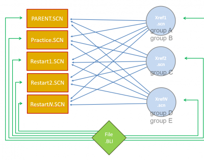
It is strongly recommended that you use external reference scenario files to avoid this. ISAT does not reset static object options in the xref file.
Added 2021.12.29 Expression Triggers and Values
Using Values in Expression Triggers
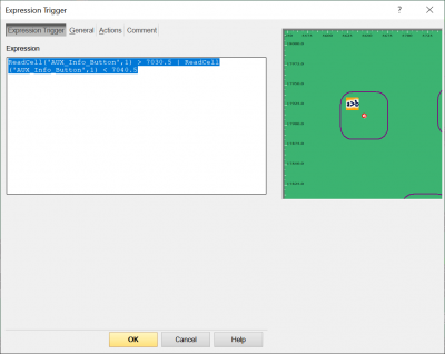
To ensure proper execution of expression triggers, it is recommended that the values used include the desired range by decreasing the lower threshold or increasing the upper threshold instead of using the exact value.
For example, to process values in a range (7031 - 7040):
Note: remember that negative values must be calculated since the expression parser does not parse negative values otherwise.
For example, to properly parse a specific transmission gear (Park): ReadCell('CFS_Auto_Transmission_Mode', 1) = ( 0 - 2 )
Rehearsal without specifying a start location
In some cases ISAT will crash if the external driver (XD)/start location has not been specified or is missing due to a sol2 file configuration error.
ISAT Overview & Interface Basics
This section contains information about ISAT and the ISAT interface.
What is ISAT?
ISAT is the DSRI Interactive Scenario Authoring Tool. ISAT is used to create simulation scenarios:
- 2D roadmap viewer
- Native file format: SCN (scenario.scn)
Requires a roadmap (BLI)
ISAT uses resource files that are based on the model objects found in the miniSim. They are proxy objects for the real models used during simulation.
ISAT contains a rudimentary scripting language for automating some repetitive tasks. Scripting is an advanced topic. Because the scripting language is not well documented, it is recommended to copy existing scripts that perform similar functions and modify them.
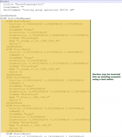
Because ISAT scenarios are text, you can make some edits quickly and easily using any text editor.
However:
When editing a scenario as text, always work on a backup copy in case something goes wrong in the text editing process that invalidates the scenario file to the point where ISAT cannot read it!
ISAT is NOT:
ISAT is not an object editor for creating or modifying 3D model objects, signs or roads.
miniSim Scenario Components Overview*
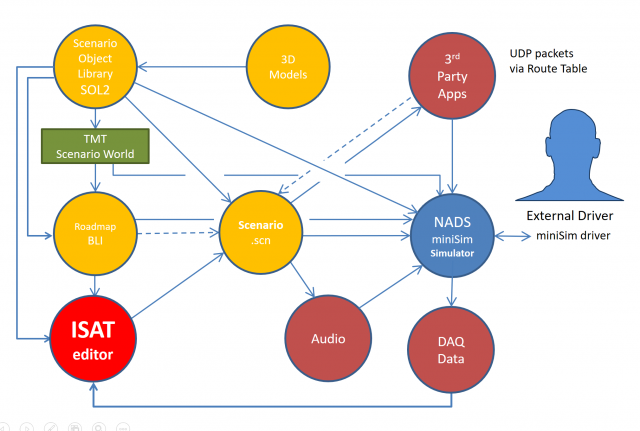
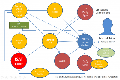
The following diagram illustrates the context of scenario authoring to provide an overview of related components.
- See the NADS miniSim user guide for miniSim simulator architecture details
TBC hyperlink to miniSim user guide & page ref
What is a Scenario?
A scenario defines everything that happens to the driver during a simulation.
Uses Actions and events to control the scenario; i.e., familiarization or restart drive, hazard detection & recognition or obstacle avoidance.
- Coupled to a roadmap (BLI)
- Scenario behaviors (responsible for executing scenarios) run at 30Hz
Anatomy of a Scenario
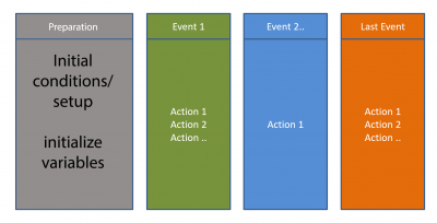
Scenarios typically have an initialization period followed by one or more events. A final event is the last event to occur before simulation is terminated.
Scenario events may contain one or more actions.
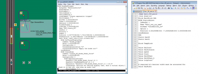
Scenario files are text files
- Can be edited by a text editor
- Portions of a scenario file can be generated programmatically:
- ISAT ISC
- Python
- Shell script
This diagram shows the same scenario in (left to right) ISAT, Emacs and Notepad++ text editors
Scenario Text File
Typically you can borrow elements from other scenario files by copying elements from one scenario and pasting them into another using a text editor or ISAT.
- If editing text, always check your edits in ISAT!
- Copy/Paste - delete paths from elements when the BLI is different between your source & destination BLI files. The following scenario elements contain paths:
- ADO (with a path specified)
- Any roadpad trigger (roadpad, Time to Arrival, Follow)
NOTE: A Traffic Source is not a portable element but it can be re-created in ISAT or integrated into a new scenario by copying the element from the source scenario then using a text editor to paste it into the destination scenario
How can I find information in multiple files easily?
Text files are easy to examine in a command (shell) window.
Example search for time trigger in all scenario files: >grep TimeTrigger *.scn | grep ISAT | grep Name <Enter>
- ISAT-Samples-Avoid.scn: Name "TimeTrigger1"
- ISAT-Samples-Avoid.scn: Name "TimeTrigger2"
- ISAT-Samples-Avoid.scn: Name "TimeTrigger3"
- ISAT-Samples-Avoid.scn: Name "TimeTrigger1"
How to know what to look for in the scenario text file?
If you know what to look for in a scenario GREP can help you locate files containing that element or text quickly.
What if you don't know what to look for? How do you find something when you don't have any idea what to look for?
- Create a new scenario
- Create the scenario element you need or are looking for:
- ADO, Trigger/Coordinator
- Give the element a unique name that you can search for in the text file
- Save the file, then edit the file in a text editor
- Find the element name to see element syntax and parameters
TBC: Insert demonstration to find an expression trigger that relates to the speed of the ownship
What is a Scenario Event?
A scenario event is made from one or more actions created to present situational information to the external driver (research participant, trainee or simulation viewer) in some logical sequence;
- force a vehicle to change speed
- force a vehicle to brake, change lanes or turn
- create or destroy scenario elements
Or:
- change scenario elements:
- initialize variables
- change traffic signal state
- etc.
- change scenario elements:
Typical Scenario Events
- When the external driver approaches a specified location, cause oncoming traffic to veer into the drivers' lane to force a driver response
- As the external driver approaches a specified location, control ambient traffic to expose a vehicle stopped in the drivers' lane
- When the Time to Arrival (to a specified location) is 4 seconds, change the traffic signal to yellow and activate traffic stopped at the intersection (aka red light runner)
What is an Action?
Actions are specific commands that happen intentionally during a simulation:
- Time, situational, calculation or location based
- Caused by the external driver or some other action, hardware configuration or calculation
- can create or delete objects, including other scenario elements
Typically actions are linked with other actions to create a scenario event as shown in the figure above.
Typical Actions
- Activate a scenario element
- Calculate something:
- -Time to arrival (TTA)
- -Time to collision (TTC)
- -headway
- Check state of simulator or driver
- Create something (any scenario element)
- Destroy a scenario element
- End simulation (terminates the current drive)
- Play a sound
- Set a variable
- Set ADO vehicle speed (not the external driver)
Adding an action to a trigger
The following example uses a Time Trigger; remember that all triggers share the same actions.
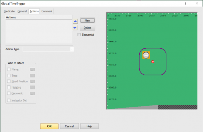
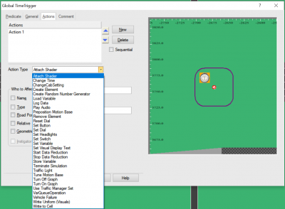
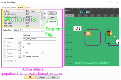
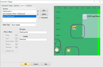
To add an action to a trigger you can double-click on the trigger, navigate to the Actions panel, and click on New to create a new action.
The possible actions are listed under the Action Type drop-down menu.
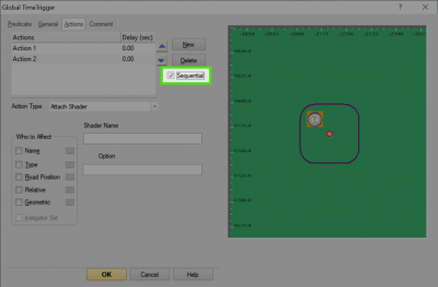
Actions are arranged in a 'stack' and are processed from top to bottom. If you use multiple actions you should enable the sequential flag to ensure each action is executed in sequence. Without the sequential flag, actions will be processed as fast as the simulator behaviors can execute.
Actions may be re-ordered in the stack using the arrows located near the action stack list.
ISAT Modes of Operation
- Edit
- Rehearsal
- DAQ playback
- Monitor Currently not available
Edit & Rehearsal Modes
- Edit - this is where scenario authors will spend the most time.
- Creation or modification of scenario
- Link to or import portions of other scenario elements
- Rehearsal
- Debug & test scenario
- Simulates scenario using Behaviors and Vehicle Dynamics
- Displays error messages from behaviors
NOTE: Rehearsal mode simulates the external driver; your simulation may not respond as expected:
- i.e., if the driver was instructed to 'remain on the right lane', the simulated ownship may not stay in the desired lane
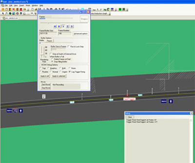
- Some control of the simulated ownship is possible in ISAT using the Rehearsal Mode >> Advanced Options panel
- speed, lane changes
Playback Mode
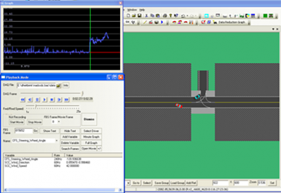
- Playback mode will play back a DAQ file from a miniSim drive
- Can search for specific conditions; i.e. CFS_Brake_Pedal_Force > 0.1
- Display data streams
- Graph collected data (limited to single cells)
- Record a video file of the playback
miniSim Scenario Components
The following diagram shows an overview of scenario related components of the NADS miniSim and how these components work together.
ISAT Workspace
ISAT uses standard Windows[TM] graphical user interface conventions such as floating windows/panels/dialogs and dockable widgets.
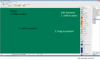
The primary region where the road network and placed scenario elements are shown is known as the workspace. In the default layout, menus are located across the top of the interface. A region of icons is located beneath the menu region. Additional ISAT widgets may be positioned along the right or left edges of the interface.
In cases where ISAT needs to place an element, notice the cursor changes to an insert element cursor when you select from menus or icons.
The menu and icon widgets require a LMB to access and place into the workspace. For the ISAT elements widget, LMB and drag the element into the workspace.
ISAT Workspace Status Bar
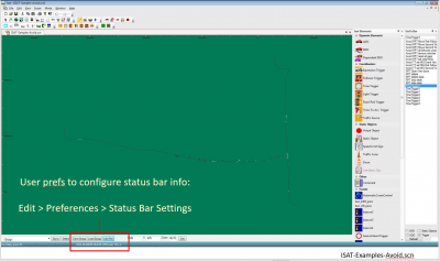
The status bar contains useful information to the scenario author:
- position (continuously reports location of the cursor)
When configured, the status bar can also report:
- Name of scenario elements
- Roadway information:
- road name
- default speed limit
- surface material code for location under the cursor
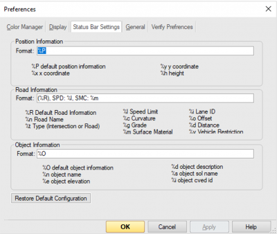
Status Bar Settings
The status bar settings can be accessed by choosing Edit >> Preferences >>Status Bar Settings. Use the existing codes to configure the status bar to display the desired information.
ISAT Iconography
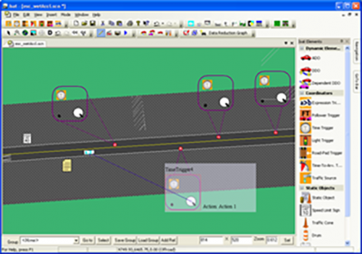
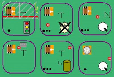
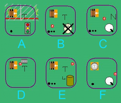
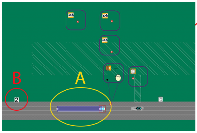
ISAT provides graphic hints for triggers placed in scenario that can be useful when editing or maintaining scenarios.
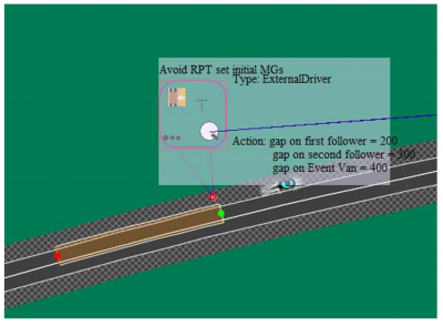
The general format is a border enclosing miniature icons of the trigger and first action contained in that trigger. Additional information representing one or many actions is also shown.
ISAT will list all trigger actions when a trigger is selected, but these hints provide a way to quickly identify what actions have been authored.
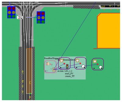
- A Roadpad trigger, one action: Traffic Light Action
- B Roadpad trigger, multiple actions, first action is Remove Element
- C Roadpad trigger, multiple actions, first action is Set Dial
- D Roadpad trigger, constrained to road (lane), no actions - this is an empty trigger
- E Roadpad trigger, multiple actions, first action is Log Data
- F Global Time Trigger, single action: Set Dial
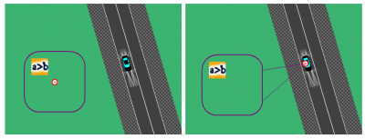
The element handle is the red dot visible in most of the triggers. The handle can be dragged into position, and the trigger will follow the handle
Drag the trigger off the handle to offset it's location from the handle
Measuring Distance in ISAT
To measure between two locations in ISAT:
- measurement is a linear measurement
Press & hold Ctrl and Shift keys, RMB on roadmap/BLI Position cursor over any other location
The measurement will update dynamically to reflect the distance from the cursor to the original 'pinned' location.
TBC link to video example
Scenario Authoring & miniSim Architecture Overview
This section contains scenario authoring documentation.
ISAT Elements
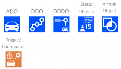
- ISAT objects consist of two main types: the objects that can be inserted using ISAT, and the objects already present in a roadmap/BLI.
1. Objects placed in ISAT
- These are objects defined in the Scenario Object Library (SOL2) and can be placed onto a roadmap by the scenario author:
- ADO
- DDO
- DDDO
- Static Object
- Virtual Object*
- Trigger/Coordinator
- Traffic Source
- NOTE: Virtual objects are defined in the scenario, not in the SOL2.
2. Scenario world objects
- These are objects that exist in the roadmap and have not been added by the scenario author. These objects may be either authorable (can be changed by the scenario author) or not (the object cannot be selected or changed in ISAT).
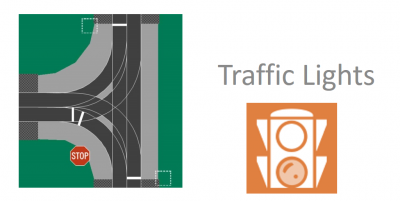
- Traffic Lights
- Traffic lights are embedded into intersections for traffic control purposes.
- The SOL2 contains a traffic light object that can be placed in ISAT; this is not a traffic light that controls traffic. It is a static object that only looks like a traffic light and can be controlled like any other static object.
- NOTE: There can be only one traffic light assigned to an intersection path. In some cases, i.e. on approach to a toll booth, multiple signals may be required visually.
ADO Scenario Object
- Vehicles that use vehicle dynamics and are AI controlled
- Exceeding vehicle dynamics capability can cause issues
- i.e., if ADO must exceed 10g's, the operation will likely fail
- failure may cause ADO to disappear or be planted into the ground or fly into the air and freeze
- ADOs are 'aware' of other simulation entities
- ADOs will attempt to change lanes to go around slow moving objects if this functionality is not disabled by the scenario author
- ADOs may halt if they cannot move around a slow moving object or change lanes
- The scenario author sets default ADO behaviors; i.e.:
- initial velocity
- turn signals
- headlights
- lane changes, etc.
- RMB on ADO to specify path
TBC insert RMB ADO menu graphic
- Actions to modify ADO behavior
- Set Dial
- Set Button
- instruct the ADO to maintain distance relative to the driver
- maintain gap
- cause the ADO to do something specific; i.e.:
- enable brake light
- accelerate or slow or stop
- change lanes
- instruct the ADO to maintain distance relative to the driver
DDO Scenario Object
- DDOs are 'dumb' objects
- Do not obey traffic rules
- DDOs follow a path blindly; also known as 'path follower'
- Are not 'aware' of other entities within the simulation
- No collision detection between the DDO and other scenario elements
- DDOs have two modes of operation:
- Follow a path using kinematics
- Free motion object
- OpenDynamicsEngine library is used to model free motion objects dynamic behavior
- bouncing/rolling ball
- object falling off back of truck
- OpenDynamicsEngine library is used to model free motion objects dynamic behavior
DDDO Scenario Object
- Includes a target that affects DDO velocity/position along path
- DDDOs are 'dumb' objects
- Do not obey traffic rules
- DDDOs follow a path blindly; also known as 'path follower'
- Are not 'aware' of other entities within the simulation
- No collision detection between the DDO and other scenario elements
Free Motion Object
A free motion object is a non-vehicle DDO that:
- need to have realistic motion
- needs to interact with the environment
- simple collision detection
- objects that fall off vehicles
- static objects on road that start moving
- rolling ball (i.e., on a hill or slope)
NOTE: vehicle dynamics do not apply to Free Motion Objects
Free motion objects have 3 modes:
- coupled
- relative trajectory
- free motion
- may require a mesh file to define a portion of the road surface to react against
Change object mode using Set Dial >> DDO >> Change Mode action
TBC insert graphic
Static Object
- Model objects are defined within the SOL2
- vehicles, animals, obstacles, signs
- any model object defined in the SOL2 as a static object
- May contain multiple visual representations
- options may be set as initial condition of the object, or changed during simulation using Set Dial action >> StaticObjManager
- Can use ADO models as static objects (as defined in the SOL2)
- Not intended to move (change position) during simulation
Traffic Signal
Traffic signals are objects with special operation and function; they are coupled to intersections and routes of travel through intersections to control traffic flow similiar to their function in the real world. Traffic signals are part of the source tile model and may not be re-positioned or physically altered by scenario except for their visual signal state appearance; i.e., red, green or yellow signals.
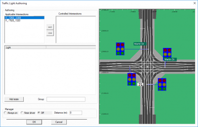
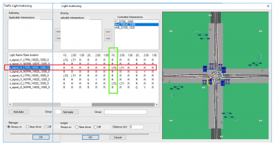
To control intersection traffic signals use Edit >> Traffic Light ManagerTraffic signals use a Signal State Table (SST) to control which signal states are active and when. Each intersection with traffic signals will have an associated SST.
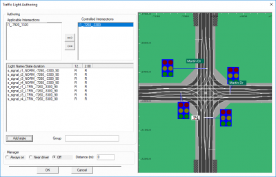
The above diagram shows an intersection in the workspace to the right, and the traffic signal state table for that intersection on the left. At this point additional states (for signal condition) can be added by clicking the Add state button.
The above diagram shows two states defined for the intersection, represented by the two columns of state condition.
Continue adding states until the desired signal cycle has been defined. Generally this consists of red, green or yellow states.
NOTE: There is currently no way to automatically author a series of traffic light signals
To author traffic signal lights in sequence or on a route, the scenario author has to manage the signal states
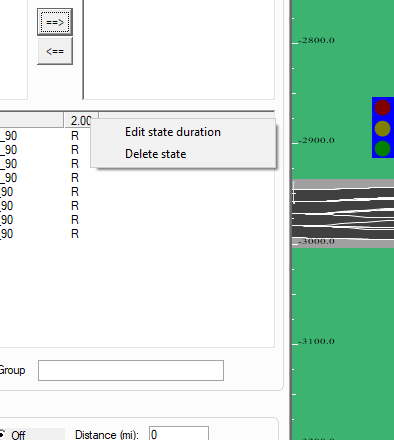
To edit the signal state duration RMB on the duration field header and choosing Edit state duration on the context menu. Enter the desired value then click OK.
Traffic Signal Types
The ISAT status bar reports Traffic Signal Type name. There are two signal types:
- Standard signal - IDs may have no identifying information
- Valid signal states: Red, Yellow, Green, Flashing Red, Flashing Yellow, OFF
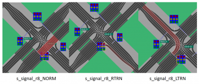
- Extended signal - The extended traffic signal type was developed to support dedicated traffic paths through intersections. These signals can be identified by the type code in their name:
- NORM (normal)
- uses standard signal states
- LTRN (Left Turn)
- signal states used should reflect signal type; i.e., Left Green, Left Yellow, etc.
- RTRN (Right Turn)
- signal states used should reflect signal type; i.e., Right Green, Right Yellow, etc.
- STRT (Straight)
- signal states used should reflect signal type; i.e., Straight Green, Straight Yellow, etc.
Changing Signal States in Scenario
Traffic signals are controlled in scenario by using a Traffic Signal Action to change the SST.
NOTE: The Traffic Signal Action works by changing the SST, not by changing the traffic signal. This is a subtle but important difference.
Setting a signal to an undefined state effectively does nothing to the traffic signal.
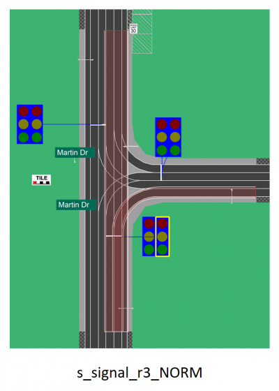
The above diagram shows a fully populated SST, with one signal row highlighted in red, and one state column highlighted in green. The associated intersection corridor is highlighted, showing the signal controls a dedicated left turn.
During simulation, the initial signal state is defined by the left column. As the simulation proceeds, the signal state changes according to the duration states defined across the state table, proceeding left to right and then wrapping around to the beginning after the last defined state. Each traffic signal appearance changes according to the configuration of the SST.
As a driver approaches this intersection, assume the signal state is in the column left of the highlighted column (Red), and the desired action is to change the signal to green.
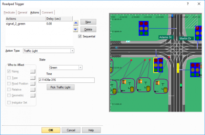
The action used to change a traffic signal state is the Traffic Light Action. Using a traffic light action requires the specification of a signal state, the traffic signal to affect, and a duration.
In the above diagram the scenario author has specified the desired state as Green as shown in the action dialog.
However, referring back to the previous state table diagram, there is no such state present in the SST. That means this particular action will fail, and the traffic signal will not change as the driver approaches the intersection - because the action does not create a new signal state, it works by advancing the state table condition (column) to the specified condition. If the condition is not present in the SST then nothing will appear to happen.
In this example, the action should be edited to use the correct signal state Left Turn Green, which is present in the SST.
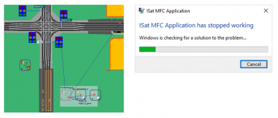
NOTE: Accessing the traffic signal action after it has been created can be problematic!
- i.e., ISAT frequently crashes when accessing the traffic signal trigger actions
Solution: Isolate traffic signal action into some other trigger, i.e. in a Time Trigger that only contains the traffic signal action. If you have to make minor edits the scenario file can be edited as text in a text editor. Major edits may require re-creating the action from scratch, if ISAT cannot access the action.
Change A Traffic Light Using Scenario Action
To change a traffic signal, use the Set Dial >> Traffic Light action. NOTE: The Traffic Light action does not change the signal directly. The action simply advances the traffic light state in the signal state table.
- If the specified target condition is not present in the signal state table, the traffic signal state does not change
This diagram shows a fully populated traffic signal state change for an intersection.
- Static object traffic lights
- These are objects, not true traffic signals and so they are not controlled with the Traffic Light manager.
Traffic Source
A traffic source is a coordinator used to create traffic at specific locations in the road map (unlike the Traffic Manager). This is useful for creating ambient traffic. Traffic Sources creates ADOs or DDOs at random or user-specified intervals.
Elements created using a Traffic Source will be created at the locations specified by the user. If traffic is specified at multiple locations the actual location for each creation will be determined randomly during simulation.
Note: Using the Relative Creation flag on ADOs created by the traffic source will not create traffic at the specified location on the map, but use the information in the Relative Creation fields to populate traffic in the scene during simulation.
This method allows for more flexibility but care must be taken not to create so many ADOs that miniSim is unable to make frame rate. Too many ADOs will cause the scene to jump and 'jitter' and it will feel slower than normal.
Virtual Object
This object has a visual representation but does not exist as a 3D model in the simulated world:
- 2D shape
- Overlay on screen of project into the scene
- supports animation (change of unique states)
A virtual object can be one of several predefined shapes or a custom image file:
- Virtual objects will draw over scene elements during simulation
- Virtual objects do not render accurately during ISAT scenario rehearsal
Custom (icon) file virtual objects
Note: Some versions of MiniSim_2.3 do not support custom virtual objects. For those installs, if you require this type of functionality, a workaround exists in the form of a 2D model that can be customized (i.e, sprite).
Virtual objects may be customized using graphics files (texture images) to display any desired custom element. This typically requires the use of a bitmap graphic. Various file formats are supported: JPG, BMP, PNG. It is possible some types of these formats may not work - in those cases, try an alternate format.
If image transparency is required and the custom icon does not display during simulation, please email dsri-minisim@uiowa.edu with a description of the issue, your scenario and custom virtual object image file.
Custom icon files must be located within the Nads MiniSim path for resources - at NadsMiniSim_x.x\data\visuals\Models\ModelTx.
Standard virtual object shapes
The virtual object shapes include:
- Circle
- Triangle
- Octagon
- Star
- Diamond
- Icon <- this is for custom virtual object graphics
- Rectangle
- Hexagon
The virtual object fill and border color and transparency can be set in the virtual object properties dialog panel.
Virtual Object Workaround
There is a scenario authoring method that can be used to emulate virtual object functionality through the use of a DDO that is coupled to any dynamic scene element, including the External Driver. One model has been created to support this method called "sprite".
Note: The sprite model is a 2D object present in the scene, and can therefore be occluded by other scene elements during simulation.
The sprite model is designed as a flat plane that continuously faces the viewer. It contains different sized planes and can be customized through textures.
When authoring your scenario, configure the sprite object to Off unless it should be visible at scenario start. During the scenario you can control the sprite appearance with a setSwitch action.
The who to effect should use the name of the DDO placed in your scenario. The switch name will be s_sprite as shown above. Any valid option can be used. An invalid option (greater than 30) will disable the sprite the same as selecting the OFF option.
Coordinators
Coordinators are used to control scenario elements:
- Intersection manager
- Controls traffic within intersections
- Traffic Light Manager
- Controls traffic light signal state (signal appearance)
- Triggers
- Traffic Light trigger
- Expression trigger
- Roadpad trigger
- Time to arrival trigger
- Follow trigger
Triggers
All trigger types share the same Action types
- IF Then conditional
- Predicate: i.e., the activating agent
- If predicate is TRUE, then do Action(s)
- Road related triggers are categorized by predicate type
- Named element
- Road (lane)
- Nth vehicle on path only
What trigger is appropriate? To determine which trigger is most appropriate, consider the task you are trying to accomplish. The differences between triggers is their activation methods.
Use this trigger when something has to happen at some point in time.
Time triggers are also useful as "placeholder triggers"; used to apply persistent actions to multiple elements with unique settings for each element. Normally a persistent action is the last action possible in a trigger since the persistent action fires continuously. Putting persistent actions into a time trigger allows the scenario author to continue an action stack in the parent trigger if necessary.
Time triggers can be used as a 'stopwatch' - elapsed time, such as ending a drive after 3 minutes by setting the trigger to fire using an Activation Delay of 180s (GTT >> General).
Often used as a placeholder for actions such as initializing variables, displaying text messages to the screen using Set Visual Display Text actions, etc.
Note: A time trigger can have global elapsed time and activation delay of 0, which causes the action stack in the time trigger to activate when that trigger is created.
Use this trigger when something has to happen at some location in the drive that does not require event timing to be comparable for all participant drivers. For cases where event timing must be comparable among all participant drivers use the Time to Arrival trigger (TTA) instead of a roadpad trigger.
Use this trigger when something has to happen relative to some point in the drive, and also ensure all study drivers experience the same event timing irrespective of driver style (conservative, slow vs. aggressive, fast). Time to arrival (TTA) trigger uses a time calculation from the trigger pad activation to a target location specified in the trigger.
This trigger activates actions when the specified traffic signal state is reached. For example, if the desired action is to create a DDO pedestrian to step into traffic when the traffic signal is yellow, then the Traffic Signal Manager must be used to author the appropriate signal states for the traffic signal.
Typically some other trigger is used to control the traffic signal (ie, to change the signal to Yellow on approach). It is therefore perfectly valid to put the actions within this other trigger rather than relying on the traffic light trigger.
Note: Once a traffic light action has been authored, ISAT may be prone to crashing when accessing that trigger. This problem can be avoided by creating a time trigger and isolating the traffic light action there, allowing the parent trigger to be modified without crashing. Adjustments can be made to the traffic light action time trigger in a text editor, or recreated if it becomes necessary to make adjustments and ISAT continues to crash when trying to make edits.
Note: The traffic light action does not change the traffic signal state, and it requires a valid state sequence to exist in the signal timing table (Edit >> Traffic Light Manager). The traffic light action will not create a signal state that does not already exist in the signal timing table.
Use this trigger when something must be monitored, evaluated or calculated such as checking a variable or cell value, velocity of the driver or the state of simulator hardware (steering wheel angle, brake or accelerator pedal position) or distance from the driver to some other object in the scenario.
Multiple expressions can be used within the same expression trigger. In those cases, all expressions must evaluate to True in order for the action stack to execute unless using an OR operator.
Use the OR operator - the pipe character "|" if you want to activate the action stack if any of the expressions evaluates to True.
In the following example, the trigger checks for TrialNumber = 1 and FirstButtonPress variables, and then checks if Aux Button 1 or 0 was pressed:
ReadVar('TrialNumber') = 1.0 & ReadVar('FirstButtonPress') = 1.0 & (ReadCell('Auxiliary_Buttons', 0) > 0 | ReadCell('Auxiliary_Buttons',1) > 0)
Note: Expressions can also be embedded into some other triggers, most notably the Set Dial >> ADO >> Forced Velocity action often used in Roadpad triggers.
Use this trigger when something has to happen based on one ADO position relative to another scenario element (including the XD). The follow trigger requires a leader and a follower to be specified; when this condition is met, the trigger action stack activates.
Note: Both leader and follower must be positioned on the follow trigger roadpad to satisfy the follow parameters.
This trigger is most useful to perform actions for off-road actors such as walkers. The trigger predicate is limited to Name or Type and requires a geometric position to be defined.
A more limited version of the geometric position trigger can be implemented with a Global Time Trigger that contains a Creation Radius. Placing the creation radius defines the area where the trigger may be activate.
Trigger Operation
One shot
- Fire trigger once only
Debounce
- Debounce is the interval between multiple trigger activations when predicate is TRUE and actions have completed execution
- Controls the 'rate of fire' of the trigger
- Debounce prevents unintentional repeat execution of the trigger actions
For example, a time trigger with a debounce of 0.96 seconds and actions that take 1 frame to complete will fire once per second.
Trigger General Settings
- Lifetime
- How long the trigger is alive (active)
- Default 0 means trigger lives unless the trigger is deleted
- Activation Delay
- Time after the trigger is created when it becomes active
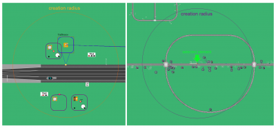
- Creation Radius
- How close the external driver has to be to the trigger before it is created
- Delete trigger when the external driver is no longer within the distance specified
- One shot
- Fire the trigger only once
- Priority
- Used with interdependent triggers to establish trigger priority:
- i.e., a roadpad trigger sets a variable, and an expression trigger reacts to that variable. The roadpad trigger should have a 'high priority', the expression trigger should be set to 'Low priority'.
- Debounce
- Time after firing the predicate remains inactive
Roadpad Trigger
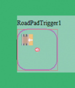
A roadpad trigger (RPT) is defined on a segment of road or intersection by a path called a road pad (or pad).
The roadpad pad defines a geographic region where the trigger can be activated.
The trigger activates when the trigger predicate steps on the pad anywhere on the pad. It is not necessary for the trigger predicate to step on the pad at the beginning (start) of the pad.
- By Name Set
- ISAT will prompt for existing scenario model object/s
- By Type Set
- Type of object; i.e., External driver, ADO, etc.
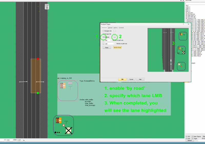
- By Road
- Filter trigger to a specific lane; i.e., predicate has to be on the roadpad and in target lane
- Can be used to implement conditional trigger activation
- An audio message to change lanes can be suppressed if the driver is already in the correct lane
Note: The highlighted lane shows which lane is the activating lane. Other lane/s will not activate the trigger action stack.
Time to Arrival Trigger
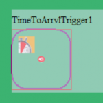
The Time to Arrival Trigger (TTA) is similar to the Roadpad Trigger and adds a timer
- Time to reach target point
- Can use an expression to calculate time
- Arrival time can take acceleration into account
Target point
- The location used to measure vehicle distance
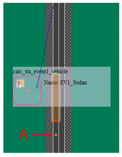
Time to Arrival Trigger example
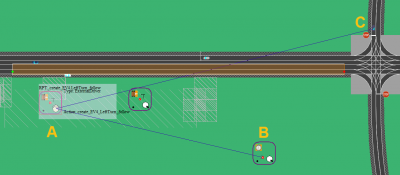
A is the target point used in the trigger calculations
Follow Trigger
The Follow Trigger (FT) is another type of roadpad trigger
- Trigger activates when vehicle A is Distance X from vehicle B
- Distance can be in feet or time
- Both vehicles must be on roadpad;
- very long roadpads are common with this trigger
- Vehicles can include the External Driver
- Expression takes priority over time field
TBC FT graphics
Additional Triggers
- Global Time (GTT)
- Elapsed time from start of scenario
- To use GTT as a timer, add an Activation Delay set to the desired elapsed time
Expression Trigger
Execute actions if input expression evaluates to TRUE; the expression is specified on the trigger Predicate tab.
Syntax
Expression triggers support a simple language syntax with operators and functions. The syntax is infix notation; i.e. a + b, not a b +.
Note: It is not generally possible to embed one function call inside another: cos(sin(x)) is therefore an invalid expression. ISAT will report invalid expressions during rehearsal of a scenario. Invalid expressions are not supported and will not operate as written during simulation.
Exception: Currently it is possible to use the square root function with GetObjDistPow2 as in the following example:
sqrt(GetObjDistPow2('Target_Object_Name'))
Multiple expressions may be combined using the logical AND (&) or OR ("|" pipe character).
Exp1 & Exp2, Exp1 & Exp2 & Exp N
All expressions must be true for the trigger to evaluate to TRUE and execute the action stack.
Exp1 | Exp2 One of the expressions must be true for the trigger to execute the action stack.
Negative values are not directly supported by the expression parser. To use a negative value, it must be a calculated value such as the following:
ReadCell('CFS_Steering_Wheel_Angle',0)<(0-5.0)
Operators
Operators are used to create expressions.
String
- Used within quotes as a string literal; i.e., 'some string'
Grouping
- Parentheses group elements together; i.e.,
- (); (a), (a + b)
Multiplication
- *; a * b
Division
- /; a / b
Addition
- +; a + b
Subtraction
- -; a - b
Note: negative values must be expressed with a subtraction operation: (0 - 5), not -5 (invalid)
Greater than
- >; a > b
Less than
- <; a < b
Logical And
- &; a & b
Both a and b, otherwise returns 0 (FALSE)
Logical Or
- |; a | b
a or b returns 1 (TRUE)
Expression Functions
Functions are used with operators to create expressions.
Function: sin
- sin -sine
Syntax
- sin(float x)
Description
- The sin() function returns the sine of x, where x is given in radians.
Return Value
- The sin() function returns a value between -1 and 1.
Function: cos
- cos –cosine
Syntax
- cos(float x)
Description
- The cos() function returns the cosine of x, where x is given in radians.
Return Value
- The cos() function returns a value between -1 and 1.
Function: ReadCell
- ReadCell()
Read a Cell value.
Syntax
- ReadCell(string Name, int Cell Array index)
Description
- ReadCell returns the value of a given cell (a cell is the current instance of a variable that will be maybe written to a daq file).
Index specifies a 0 based index into the array. Since most cells are single element arrays, a value 0 indicates the first element.
Cells valid for the ReadCell function are defined within the cell collect file NadsMiniSim.cec located in the miniSim_x.x\data folder. The ReadCell function operates on shared memory during simulation, it does not read cell data from the DAQ file.
Cells that are defined may be written to the DAQ; the collect file specifies which cells are saved into the DAQ and what frequency to use for the write operation. The NadsMiniSimCollect.general.txt file is located in the miniSim_x.x\data folder.
Available Cells: Any cell that has been defined in the .cec file. For example:
- LogStreams: Array of 5 floats. Logstreams are a set of values the scenario author can write to through “write to logstream” actions.
- AccelPedalPos: Single Value. The current position of the accelerator pedal
- BrakePedalForce: Single Value. The current force on the brake pedal in pounds
- SteeringWheelAngle: Single Value. The current rotation of the steering wheel
- CruiseControl: Single Value. The current cruise control position. (values are cab/platform specific)
- TurnSignal: Single Value. The current position of the turn signal (values are cab/platform specific)
- OvVel: Single Value. The participant’s current speed in miles per hour
- OvLaneDev: Single Value. The participant’s lane deviation in feet.
- OvHeadwayToLeadVeh: Single Value. The distance in feet to the first vehicle in front of the participant. -1 if no vehicle can be found.
- OvTtcToLeadVeh: Single Value. The time to collision to the first vehicle ahead of the participant.
- Horn: Single Value. The state of the horn (values are cab/platform specific)
- DynObj_Vel: Array of 20 floats. The speed of a given dynamic object. Dynamic Objects are sorted in terms of distance to driver.
- OvVelLocal: Single Value. The participant’s current speed in miles per hour, using the value local to scenario control
For a complete list of cells and array elements please see the miniSim data dictionary spreadsheet.
Return Value
- Returns the value of the specified cell.
Example ReadCell(‘LogStreams’,5) > 3
Function: CellEquals
- Cell Equals, array element, value to compare
Syntax
- CellEquals(string name, int index, float value)
Description
- The Cell Equals function is similar to the ReadCell function, except it adds an additional value to compare against the cell value.
Like ReadCell, name specifies the name of the cell, index specifies the cell array index (use 0 for single value cells).
Available Cells:
- Any cell that is defined in the .cec file.
Return Value
- Units: 1 or 0
- 1 if the cell value is equal to the passed in comparison value; otherwise 0
Function: GetObjDistPow2
- Get object distance squared
Syntax
- GetObjDistPow2(string name)
Description
- GetObjDistPow2 returns the distance squared between the external driver and the dynamic object specified by ‘name’.
Distance squared is used to avoid having to perform an expensive square root calculation every frame.
If the specified object cannot be found, a value larger than 100 million is returned.
Return Value
- Feet; Distance in feet measured from the eye position of the driver to the CG (centroid) of the dynamic object specified.
A very large number is returned if the specified object cannot be found (larger than 100 million)
Example
- GetObjDistPow2(‘OncomingCar1’) < 2500
Note: To get an actual distance, multiply by the square root (sqrt())
- sqrt(GetObjDistPow2('Target_Obj'))
Function: GetObjTtcToOv
- Get Object Time To Collision to Own Vehicle
Syntax
- GetObjTtcToOv(string object name)
Description
- GetObjTtcToOv gets the time to collision from the dynamic object specified by the name parameter, to the own vehicle.
Return Value
- Unit: Seconds
- Time (seconds) to collision from the own vehicle to the dynamic object specified by the name parameter.
- 0 is returned if the object specified cannot be found.
Function: GetObjVel
- Get Object Velocity
Syntax
- GetObjVel(string object name)
Description
- GetObjVel gets the velocity in meters per second of the first dynamic object with the name specified by the ‘name’ argument.
Return Value
- Unit: Meters per second
- The speed of the specified dynamic object; 0 if no object is found
Note: Multiply by 2.23694 for miles per hour.
Example
- GetObjVel(‘PullOutVeh’) > 15.4
Function: Rand
- Random
Syntax
- Rand(int value)
- Rand(string name)
- Rand(string name, string type, double parameter, double parameter)
- Rand(string name, string type, int parameter, int parameter)
Description
- Rand returns a random value specified by the name of the generator, the type of distribution and its parameters.
If the user does not specify the name of the generator and only specifies a number as the only parameter, the Rand function will use a default random number generator to produce random numbers.
If the user only enters the name of a user created random number generator, the random number generator will produce a value between 0 and 1. If a name of generator is supplied that has not been created, the Rand function will display an error message in the ISAT debug window and return 0 (during scenario rehearsal).
The rand function supports multiple types of distributions that can be used to generate a random number.
Types of Distributions:
- normal: Normal Distribution(mean, standard deviation). The normal distribution generates random numbers near the mean with a specific standard deviation.
- gamma: Gamma Distribution(alpha, beta). The gamma distribution generates a random value that models waiting times for the Poisson process.
- uniformInt: Uniform Integer Distribution(min, max). The uniform integer distribution generates a random integer number between the lower and upper bounds.
- uniform: Uniform Real Distribution(min, max). The uniform real distribution generates a random floating point number between the lower and upper bounds.
The values stated in the parenthesis above are the parameters for each distribution in order. If the incorrect number of parameters are entered or if they are entered incorrectly, the debug window in ISAT will display an error message and the rand function will return 0 (during scenario rehearsal).
If the distribution is entered incorrectly, the debug window will also display an error message.
Return Value
- A random value from 0 to 1 if the type of distribution is not specified.
If the type of distribution is specified, returns a random value determined from the type of distribution and the given parameters.
Example
- Rand(‘myRandGenerator’,’uniformInt’,1,10)
- This example returns a random integer value from 1 to 10.
Rand(5) or Rand(‘myRandGenerator’)
- These examples return a random value between 0 and 1.
Function: sqrt Square root
Syntax:
- sqrt(parameter)
Return Value:
- return the square root of the specified parameter.
- parameter can be another function, such as GetObjDistPow2()
Function: ReadVar
- Read a variable
Syntax:
- ReadVar(string Name)
Return Value:
- Returns the string value of variable specified in <variable_name>
Traffic Light Trigger (TLT)
Execute actions when target traffic signal is set to target state; when the traffic signal state matches the target state, execute actions.
Audio Components
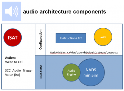
The components of the Audio sub-system includes configuration and data files installed into the NadsMiniSim_x.xx\data\sound\DefaultCabSound\Instructs folder.
The audio engine contains multiple channels and has a theoretical limit of 512 simultaneous sounds.
NOTE: Not all .wav files are compatible with the Audio Engine.
Scenario World Objects
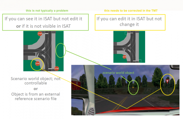
Scenario world objects are defined in the tile model source. They are not added by the scenario author since they are objects already present in the roadmap/BLI.
Typically, but not always, these objects can be authored in ISAT. However, some scenario world objects have no options - these cannot be selected in ISAT; therefore such objects cannot be authored.
Removal of world objects requires editing the source tile model using a 3D application. In some cases an alternate tile model is available identical to the original but without objects.
Contact NADS if removal of a world object is needed.
Other scenario world objects, such as Traffic Signals, are specialized function objects that can be authored. Traffic signals are authored using the Traffic Light Manager: Edit >> Traffic Light Manager.
Troubleshooting Scenario Objects That Reset
Scenario World Objects
Scenario world objects are already present when you create a new scenario - they are not added by the scenario author. These objects may be visible in miniSim but not in ISAT, or they may be visible in ISAT and seem to be controllable, but the objects 'reset' to their defaults when viewed on miniSim.
The objects which 'reset' are a symptom of settings in the TMT that are not configured to allow scenario authoring of objects.
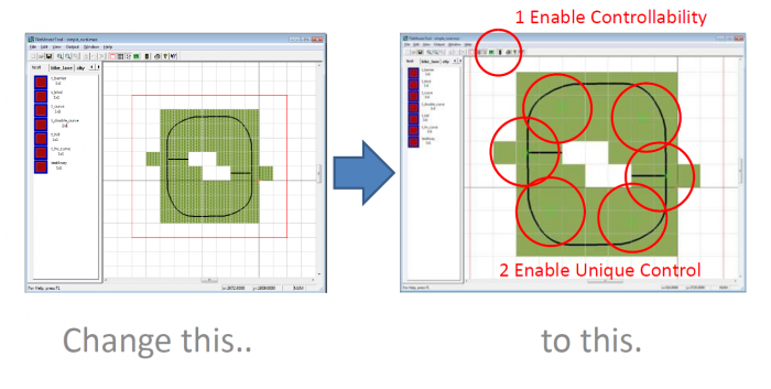
When objects appear to 'reset' or if you can edit an object in ISAT but don't see your changes in miniSim, correct the problem by resolving controllability in the TMT settings: https://www.screencast.com/t/ZH5Dh178.
Scenario Coordinate Types
There are two types of coordinates used in scenarios. The first is roadway coordinates. These coordinates are contextual (tied to a specific road or intersection and position) and are used for ADO objects and roadpad paths in general.
After a roadway coordinate has been generated, it is not updated unless the scenario author makes changes to the start, end or location of the entire path or pad.
Roadway coordinate are the reason it is not possible to change a roadmap using the TMT and expect a previously authored scenario to work on the altered roadmap. If the length or location of a road changes, the path/pad will update to the extent possible.
If the road has been eliminated and no longer exists in the roadmap/BLI, ISAT will report an error and not open the scenario file.
A. Field breakdown: RoadPos keyword <name of road:lane:position on road:path length>
Name "Ado1"
 RoadPos "r1_-6600_4620:0:5737.06:0.00"
 Path "R:r1_-6600_4620:0[5736.06:5873.83]"
B. Name "VirtObj"
 Option 2
 Position -6.8375599E+002 5.6331237E+003 0.0000000E+000
The second type is world coordinates, which are Cartesian coordinates with X increasing to the right, Y increasing forward, and Z increasing up.
Scenario Authoring
Scenario authoring is the creation, editing and testing of everything that happens during a simulation drive.
Cell Operations: Best Practice
Reading and writing to cells is a computationally expensive process. Best practice is to centralize all the reads/write to one place so that it’s only done once per cell.
Once a cell is read, the value is copied to a variable and only the variable is used throughout all the triggers that need it.
The same process applies to writing to cells. Use of variables can reduce the Cell Operations overhead greatly.
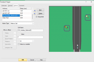
How to write to a specific cell array element?
To write to a specific cell array element, enclose the array element in square brackets as shown below:
Before You Begin
Before beginning a scenario, it is necessary to understand the following requirements:
Drive Requirements
How long is the drive? What type of roadway? Are there any specialized road elements (intersections, interchanges, freeway ramps)? Are there any environmental requirements (should the simulation replicate a real world location, or is a generic environment acceptable)? Is there a particular roadway configuration that is needed (long straight rural road vs. typical urban environment with intersections, signals, etc)?
Traffic Requirements
What types of traffic will be needed? Will ambient traffic interact with the external driver? What types of interaction will be required (traffic cloud, lead vehicle, follow vehicle)?
Events
The purpose of an event is to present a situation to the external driver. In order for the simulation to produce meaningful data, it is critical that events unfold for each driver in a comparable way. Therefore, each event must be designed with this repeatability in mind.
NOTE: one of the most variable scenario elements is the driving style of each external driver: how conservative or aggressive they drive, velocities throughout the scenario, how comfortable the driver is travelling with simulated vehicles, etc.
Repeatability often includes static elements (each driver encounters scenario elements in the same location) or in cases where the driver performance is taken into account, accommodation of the driver dynamic (velocity, lane position) through the use of time to arrival triggers (TTA) or follow triggers. A TTA trigger will fire based on time to a target location - thus a driver travelling at 45mph or a driver travelling at 55mph can both experience the same action relative to that target location, irrespective of the different driver velocities.
Beginning A Scenario
All scenarios designed to be driven require a start location - the place where the driver will be located when the simulated drive begins.
To insert a start location into a scenario:
- Insert >> External Driver >> LMB on road, intersection or terrain object
NOTE: scenarios that only contain data and are not intended to be driven - for example, signs or traffic that are used as external reference files do not require a start location, since that will be defined within the parent scenario.
Initial Conditions
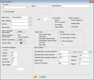
Initial conditions define how the simulated scene is configured: will the drive occur during daylight or night time conditions? Will the ownship (external driver vehicle) have headlights enabled? What type of vehicle will it be? Will there be objects or traffic visible to the driver? These form the initial conditions of the simulation experience. Additional initial conditions would include initialization of variables or establishing networked communication as needed by the scenario.
By default ISAT sets the initial condition Time of Day to 12:00 noon. The time of day is controlled from the Initial Conditions dialog:
Edit >> Initial Conditions
Scenario Authoring: Actions
Actions are the scenario elements that make things happen during simulation. Actions do specific things, like display a text message on screen for the driver, create a scenario element, change the velocity of simulated traffic, change a traffic signal, etc.
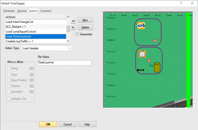
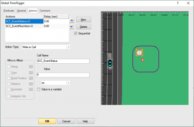
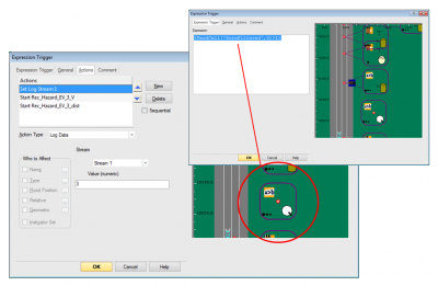
The diagram above shows the action panel for left to right: an expression trigger, a roadpad trigger and a global time trigger showing different panels based on the actions present in each trigger.
NOTE:Actions can be created, edited or removed from the Actions panel of any trigger.
NOTE: The Actions panel changes based on the action type created. When multiple actions have been defined, control the sequence of actions by changing the action order in the list using the up or down arrows next to the list.
If multiple actions need to happen in a specific order, set the order using the arrows and then flag the action list as sequential. This instructs behaviors to process the actions in the list order.
Using a delay for any action will pause processing of the following actions; the action happens first, then the delay is applied.
Scenario Authoring: Action Types
There are two types of actions:
- Instantaneous - the action takes up to one frame to complete, i.e.:
- set target velocity
- write to cell
- Persistent
*Persistent actions do not end, or take multiple frames to complete:
- Forced lane offset
- Forced velocity
- Maintain Gap
Actions
- The "Who to Affect" field defines what is affected by the action
- Instigator set: who activated the trigger
- Name: one or more named elements
- Type: Apply changes to all objects matching the specified type
- Relative: Position relative to the trigger location
- Sequential
- Actions to execute sequentially, one after the other
- Specify delay between actions
- Action executes, then delay
- Some actions are persistent and never "finish"
Scenario example: display text & roadpad trigger to stop the drive
This scenario is very simple and contains a global time trigger (GTT) that tells the driver what to do. After the driver travels along the roadway, a roadpad trigger (RPT) is used to tell the driver to stop driving. The same RPT also creates an expression trigger to terminate the drive.
TBC example scenario file
Because the external driver is not under control except by instructions, it's possible they might ignore the halt message and continue driving. A second failsafe RPT then terminates the drive.
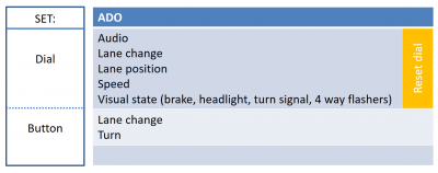
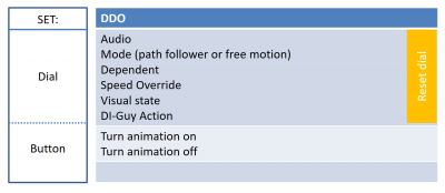
Actions: Button vs. Dial
- Dial changes a setting
- Button: always runs in a single frame
- -"immediate" change. Typically buttons have less control than a Set Dial action
ADO Actions
DDO Actions
External Driver Actions
External driver behavior can be influenced by reinforcing scenario actions through audible speeding alerts, on-screen text instructions and messages or audio instructions.
Driving behavior can be influenced with situational elements
- Car in the drivers blind spot
- Lead vehicle
- Aggressive following vehicle
- Temporary lane closure
- lane specific instructions
Scenarios should not rely on specific driver actions to be successful
- to the extent possible; sometimes you do need the driver to respond/behave in a controlled manner.
- A work zone blocking one lane typically will require a roadpad placed upstream from the work zone to shift traffic into the correct lane
NOTE: Controlling driver actions should be an experimental design consideration.
Special Actions
These actions need special handling:
- Reset or "toggle":
- Audio
- Display Text
- Ado
- Audio State
- Forced Velocity
- Maintain Gap
- Visual State
- If using these persistent actions, place them at the end of an action sequence (because no action following these will execute):
- Forced Lane Offset
- Forced Velocity
- Maintain Gap
- Visual State
- Note: If the Visual State action contains a duration then it will be handled as a normal action, with subsequent actions firing after it. However, if there is no duration supplied with the Visual State action it behaves like a persistent action, and nothing following it in the Action stack will ever fire.
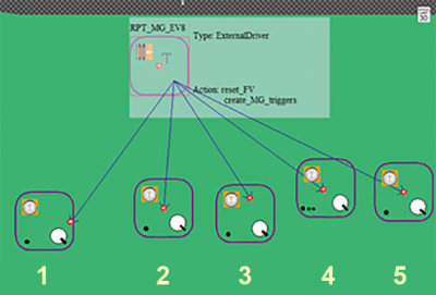
The diagram above shows how one parent trigger can be used to create multiple simultaneous triggers
- How to activate multiple unique force velocity (FV) or maintain gap (MG) actions:
- create the needed triggers from a general parent trigger, 1 per action
- put common actions into the parent trigger
- reset FV
- reset MG
Scenario Authoring How To
This section contains simple examples for various typical scenario situations.
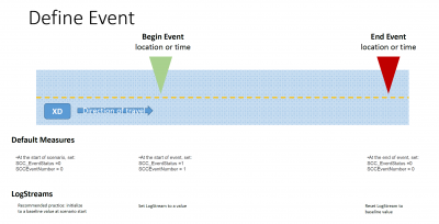
How do I specify an event?
First, determine which method is best for you - the default measures (limited measures, 20 events max) or logstreams (all simulation data, no event maximum).
Regardless of method, you specify an event by identifying areas of significance in the drive and marking them so the data within the event region can be processed. Any trigger combination that can specify event start and event end may be used.
How to know Which Coordinator or Trigger I need?
The answer to this question lies in the type of information needed for an event:
- Time
- global time trigger
- or an expression trigger that calculates time
- Position or Location
- roadpad trigger
- or a time to arrival (TTA) trigger
- or an expression trigger that calculates distance
- Calculation
- Expression trigger
How to Instruct the External Driver
Instructions to the external driver can be accomplished by three main methods:
- Instruct the driver using experimental protocol (instructional or briefing presentation)
- Information messages displayed on screen: Action: set visual display text
- Information messages delivered as audio messages: Action: write to cell > SCC_Audio_Trigger ><audio ID>
How to Add Traffic in the Scene
Generating traffic will happen in one of 5 ways:
- Created explicitly by inserting ADO, or copy/paste existing ADOs
- Created with a script
- Via a Create action inside a trigger, or placing scripted traffic inside a create action within a trigger
- From a Traffic Source*
- From the Traffic Manager**
Each of these methods has advantages and disadvantages.
Create Explicitly
The biggest advantage with this method of traffic creation is the high degree of control the scenario author has over:
- location of the created ADO
- Name of the created ADO
- Travel path of the created ADO
- Control when each ADO is created within the scene via Settings >> Creation Radius
The disadvantage is that creating a high volume of traffic will take some work with this method.
Created with a Script
This method combines the advantages of Creating Explicitly with volume. It is possible to create a large volume of traffic very easily with a script.
Disadvantages of using high volumes of traffic with a script: in the event it becomes necessary for a high degree of control over these ADOs, more is not better because ADOs will adapt to road conditions under their own power, unless the default ADO settings have been modified: lane changes, including lane changes to accommodate freeway ramps velocity adjustments
Via a Create action inside a trigger
Combines the advantages of the previous 2 methods with control over when to activate that traffic using a trigger action.
Disadvantages: Creating too many ADOs at one point in the drive can cause the miniSim to bog down for a few frames. If too many ADOs are present and active in the simulation at one time, this can cause the miniSim to drop frames and run sluggishly. This is highly noticeable and may increase the potential for the External Driver to experience simulator sickness.
From a Traffic Source
Traffic Sources rely on two methods to populate a scene with traffic:
- location specific, with each ADO created for a traffic source being a 'spawn location' for ADOs, or
- location agnostic if the ADO has relative creation enabled, thus being created relative to the object identified.
In addition to being created relative to a scenario element, ADOs are created relative to the specified scenario element:
- In front of (Longitudinal Distance > 0, where the number is feet offset from the object) , or
- Behind (Longitudinal Distance < 0, where the number is feet offset from the object).
Advantages: Can easily populate traffic into the simulation.
Disadvantages: It is easy to generate more traffic than the simulation can maintain at 60Hz frame rate, thus introducing frame lag with the resulting scene 'stutter' and the increased risk of simulator sickness.
Also, traffic created from a Traffic Source is generic traffic. It is not possible to reliably refer to specific ADOs generated from a traffic source except by using Who To Affect >> Relative (versus referring to a named ADO, i.e. Slow_Moving_Lead_Vehicle). Referring by name to Traffic Source generated ADOs will affect all similarly named ADOs at the same time.
From a Traffic Manager
The traffic manager interface is problematic in ISAT versions up to 1.8.5, especially when specifying the set of vehicles to be used for generating traffic.
Advantages: Create generic ambient traffic easily.
Disadvantages: Has the same disadvantages as traffic created via a Traffic Source. Also getting a traffic set working by specifying the vehicles to be used within the set. ISAT versions up to 1.8.5 exhibit instability when setting vehicles in ISAT.
Traffic Manager Set workaround: Borrow a working set from an existing scenario or group. Alternatively use a version of ISAT (1.8.6 +) to create the traffic set. This can be saved as a scenario or group file, which can then be used with ISAT 1.8.x as long as there is no attempt to adjust the vehicle weights within ISAT. The scenario or group file can be edited as text in a text editor, but care must be exercised to avoid introducing errors into the file. ISAT will not read invalid scenario or group files.
Traffic generated by the Traffic Manager is controlled through the use of Input Sets. An input set is a collection of vehicles and weights used to populate the scene during simulation. This is how the scenario author can control the vehicle population (type and number), density and creation/deletion distances - these attributes are unique to each set.
Since there is no 'discontinue traffic manager' function, one can be implemented by defining an input set with no traffic (an empty input set). An appropriate name can make the purpose of the set clear: PauseTraffic, Stop_TM, etc.
Sample Traffic Manager Set
This is a sample traffic manager set that can be pasted into a scenario file after the HCSM VehFail section. Be sure to paste after the HCSM VehFail end tag (&&&End&&&) in your scenario file.
Note: A scenario file may contain only one Traffic Manager section.
There are two input sets in this example; note how they contain different vehicles and different settings from each other.
HCSM TrafficManager
 GroupName "Traffic Manager"
   HCSM InputSet
     Name "ONE"
     MinDensity 3.0000000E-002
     MaxDensity 7.0000000E-002
     MaxObjects 9
     CreateDist 2.0000000E+003
     DeleteDist 3.0000000E+003
     AbsDeleteDist 3.4000000E+003
     RunFreq 1.0000000E+000
     SolWeights "cargill_semi_peterbilt_blu:2" "cargill_semi_freightliner_red:1" "cargill_semi_peterbilt_yel:3" "DumpTruck_org:3" "semi_peterbilt_yel_Walmart:2" "Cadillac_Escalade:10" "Ford_F150Xcab:15" "Saturn_Vue:10" "FordTaurus:15" "Escape:15" "DumpTruck:2"
   &&&&End&&&&
   HCSM InputSet
     Name "TWO"
     MinDensity 1.0000000E-002
     MaxDensity 3.0000000E-002
     MaxObjects 4
     CreateDist 2.5000000E+003
     DeleteDist 3.3000000E+003
     AbsDeleteDist 3.5000000E+003
     RunFreq 1.8000000E+000
     SolWeights "Taurus2011:12" "Cadillac_Escalade:16" "Ford_F150Xcab:24" "Saturn_Vue:14" "Escape:6" "Deville:24" "Audi:4"
   &&&&End&&&&
&&&&End&&&&
Managing Traffic Manager Input Sets
During simulation, Input sets are controlled by the action Use Traffic Manager Set. A set name must be provided for this action to work.
Traffic Manager generated Traffic
ADOs will populate the road network around the XD based on the parameters of the Input Set. Typically traffic is removed from the scene shortly after passing the XD. This is visible in the rear view mirror. There is currently no way to adjust this delete distance.
Traffic Manager Traffic on 2 lane freeway
Traffic will prefer to be in the XD lane, so ADOs created in any other lane will tend to veer into the XD lane. On a divided highway, traffic is generated moving with the XD.
Traffic Manager Traffic on 2 lane road
Traffic is generated in the oncoming lane. In some cases traffic may be generated then immediately removed in front of the XD.
How to Control Objects in the Scene during Simulation
"Set and forget" options on simulation entities only require the scenario author to "initialize" the element to a desired setting and then it is left alone during simulation.
Controlling objects dynamically during simulation requires the scenario "talk to" each object with a scenario action. This section describes how each scenario object type can be controlled during simulation within a scenario.
All models used in ISAT are listed within the Scenario Object Library (sol2).txt files. Terrain switch names are displayed in the ISAT workspace.
All model switches are listed within the NadsMiniSim_x.x\bin.x64\ModelList.txt file.
Note: The diligent reader will note discrepancies in model names between the sol2 and ModelList files. This is because the ModelList file contains actual file names, and the sol2 files define a "name label" for models that may, or may not, be the actual model name. Objects are linked between the sol2 and ModelList files through the ModelID/CigiID records. These values will match between sol2 and ModelList files, but IDs are not necessary at this time for scenario authoring purposes.
Complicated object names can be retrieved from the LRI file that was used to build any scenario file; each BLI is preceded by an LRI. The LRI contains all of the terrain models that will be present in ISAT. These are typically speed limit signs, traffic signals or other features that may be controllable.
Note: this file may not be present for the Springfield.bli file.
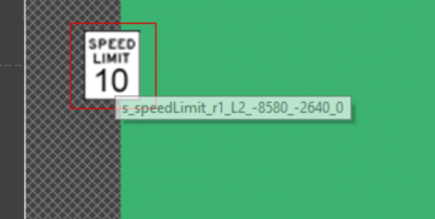
An alternative is to capture a screenshot of the ISAT workspace with the element name string showing. By default ISAT reports the name of any objects when the cursor passes over the object, as shown in this example:
| Date | Nads miniSim version | Object Type | Scenario Action | Who To Affect | Value | Notes |
|---|---|---|---|---|---|---|
| Oct. 28, 2021 | 2.3 | |||||
| Static Object (terrain) | SetDial > StaticObjManager > Set Option1 | StaticObjManager | switch name : switch option | Switch names are listed in bin.x64\ModelList.txt | ||
| Static Object, multiple options | Set Switch | Name of element | switch option | |||
| Obstacle, multiple options | Set Switch | Name of element | switch option | Switch names are listed in bin.x64\ModelList.txt | ||
| DDO, multiple options | Set Switch | Name of element | switch option | Switch names are listed in bin.x64\ModelList.txt | ||
| ADO | Set Dial > ADO > VisualState | Name of element | Limited to options present in ISAT | |||
| Traffic Signal | Traffic Light | Assign action to element | Target state | Target state must exist within the Traffic Light Manager intersection timing table for the specified signal |
How to Control Simulated Vehicles
The scenario author can control simulated vehicles by controlling the environment:
- change a traffic signal to cause an ADO to stop or start at intersections
- affect other ADOs to cause a target ADO to respond
- assign a path for the ADO to travel
Direct control:
- Lane related:
- Set button > ADO > ChangeLane, Turn, ProjectAndResetLane
- All other controls:
- Set Dial > ADO > AudioState, ForcedLaneOffset, ForcedVelocity, InhibitLaneChange, LaneChange, MaintainGap, TargetVelocity, VisualState, AudioState
How to Change ADO Velocity
ADO velocity can be changed using the SetDial action:
- SetDial > ADO >
- ForcedVelocity
- ForcedVelocity using an expression:
# match external driver speed
expr  % OvVel(0) %
# multiply external driver speed
expr  -1 9 %ReadCell('OvVelLocal',1)*1.75  %
- TargetVelocity
Indirect Control (dependent on other scenario element):
- MaintainGap
How to Link ADO Velocity to Something Else
ADOs velocity can be linked to other ADOs or the external driver using the MaintainGap (MG) action.
SetDial > ADO > MaintainGap
When using a traffic cloud containing multiple ADOs, each ADO in the cloud needs a unique MG. IF multiple ADOs have the same MG settings they will attempt to satisfy their parameters and likely oscillate position in a visually obnoxious way.
How to Author Loop Scenarios
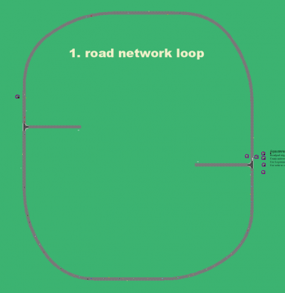
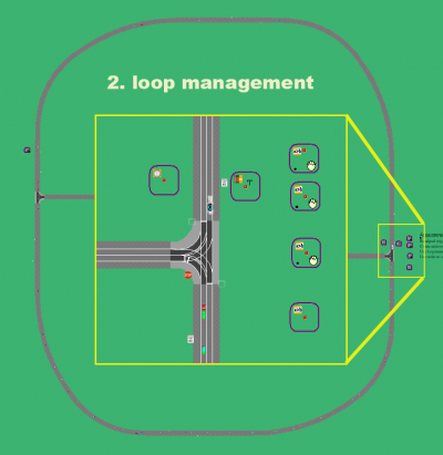
A scenario created on a loop road network operates very much like any other scenario, with the exception that it is likely to require tracking the number of times through the loop, or to present scenario events to the external driver depending on each loop context.
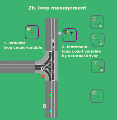
The simplest method of tracking loops is the use of a loop counter variable. This variable can be set by the driver "stepping onto" a roadpad trigger or it can be initialized through the use of a timer or expression, with increments managed by a roadpad trigger. Each time through the loop increases the loop count variable.
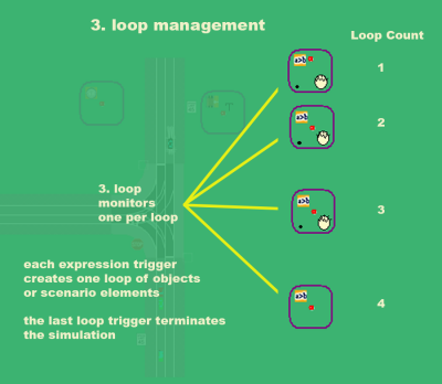
Thus it becomes possible to create events for each loop based on the loop counter variable, typically through an expression trigger.
Loop management triggers
Loop management trigger detail one
Loop management trigger detail two
Creating Loop Specific Traffic
Creating loop traffic is slightly more complicated due to the number of objects to be created and potentially the size of the actual loop. A small loop is installed with the Nads miniSim as simple_rural1 or simple_rural2. Each is a loop road network with two signed 3-way intersections.
Loop specific traffic can be created through the use of a variable (i.e., LoopCount) or within the roadpad trigger that is incrementing the loop count variable. Both methods will incorporate a Create Action that creates the required elements.
How to Change Environment Settings
The scenario author can define global or localized environment conditions.
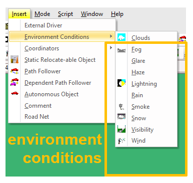
1. Insert >> Environment Conditions >> <chosen condition>
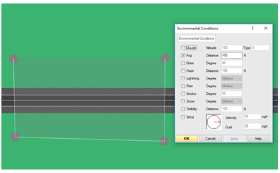
2. Define a region where the environment condition is active:
- LMB to define polygon points
- RMB to exit point entry mode
Choosing an environment condition
Environment region defined and parameters panel shows available options
NOTE: The environment condition boundary is a discrete threshold. Condition A will be on one side of the threshold. Immediately after crossing the boundary, condition B will be displayed.
How to Fade an Environment Condition
To fade gradually between two conditions requires the use of an expression that continually monitors the desired condition and sets a few variables based on the results.
Examining the demo scenario is the best way to look 'under the hood' to see exact command syntax and values to be used.
Note: this approach has been used for fog and visibility. It is unknown how it might work with non-visibility conditions such as precipitation and wind.
- From the scenario demo_visibility_transition.scn
Note: although the example above uses an environment condition boundary, it is possible to omit the defined region, retaining all commands and the scenario will still function. However, without the environment region, it becomes more difficult to determine where conditions are different from the standard settings.
How to Control a Cab Instrument Panel icon
In order to control the instrument panel, there are 2 requirements: The specific cab used for the scenario The specific control (switch) to be manipulated The action for addressing the instrument panel is ChangeCabSetting
Instrument panel models are located in NadsMiniSim_x.x\data\Visuals\Instruments These files are in OpenFlight format. Any 3D editor capable of reading or importing OpenFlight can be used to review these files. NADS uses the Presagis product Creator[tm].
An alternative method to inventory switches is to use the the buildscl.exe tool. To run the tool, open a CMD window to the IP folder location above, then run the command: buildscl <input_file.flt><Enter>. <input_file.flt> is the name of the file to process, without the '<>' characters. <Enter> means to press the Enter key,
The result will be in a new file ending with .scl. This is a text file, and can be opened in a text editor or you can use the shell utility more to view the file contents:
more <input_file.scl> | grep switch<Enter>
An example for the malibu cab is shown below. .
switch s_LowWasher 0 switch s_Cruise 1 switch s_LeftTurn 2 switch s_RightTurn 3 switch s_FwdCollisionWarn 4 switch s_BlindSpotWarn 5 switch s_LaneDeviationWarn 6 switch s_RearCollisionWarn 7 switch s_HighBeamHeadlights 8 switch s_SeatBelt 9 switch s_UpArrow 10 switch s_Airbag 11 switch s_CheckEngine 12 switch s_CheckGuages 13 switch s_ABS 14 switch s_Brake 15 switch s_LowFuel 16 switch s_Gear 17
These controls may be accessed directly in scenario using the ChangeCabSetting action.
NOTE: Some functions such as Cruise, Gear, High beam headlights, Blind spot, collision, lane deviation warnings are normally controlled not by direct access as described here but by hardware mechanisms/buttons.
NOTE: For altering cab instrument panel operation it will be necessary to modify the OpenFlight model to include the desired funationality; for example, instrument panel blanking is not build into the model but can be added by editing the cab instrument panel model file then installing the modified file into miniSim.
Scenario Hints
The total number of scenario elements active at any given time can affect simulator performance:
Total number of active elements
- vehicles (ADOs), triggers, animations, etc.
Object management
- Use paths to shift ADOs away from the driver route of travel as they turn off the route
- reduce the number of vehicles in traffic cloud surrounding external driver
- use creation radius to limit the number of active elements, and to remove elements after the driver has traveled beyond the creation radius
Creation radius works by activating the scenario element only when the driver is within the radius. The scenario element is created when the driver enters the creation radius, and is deleted after the driver leaves the creation radius.
Exploit environment to reduce object load
- Use curves, hills, intersection corners to mask objects
Object deletion
- Remove objects when no longer needed
When creating dynamic elements, create them as close to where they are needed as possible.
How to Determine When ADOs are Visible to the External Driver
Some development/setup testing may be needed to determine precise location/distance/speed; i.e., locating ADOs for a freeway ramp merge event where the external driver is merging onto the freeway with other ambient traffic present.
Unless the purpose of the event is to study driver behavior at the merge, ideally the scenario will be authored to have ambient traffic on the freeway but not to present a conflict at the merge for the external driver.
A straightforward way to determine where the ADOs are first visible to the driver is to mock up a scenario placing colored ADOs along the freeway with a velocity of 0. This will ensure the ADOs remain stationary while the scenario author determines where they are first visible to the external driver.
Place the start position/external driver far enough up the ramp to be a reasonable test for the actual scenario.
As you drive the ramp, see which ADO is first visible to the driver. Place ADOs just out of view (upstream) of that location.
NOTE: use test vehicles of the same type and character as the intended scenario vehicles. For example, do not use a sedan test ADO for a larger vehicle (SUV, bus, dump truck). Doing so will invalidate the visibility test, because a larger ADO will be visible over a longer distance than a small ADO.
At the scenario start location, ADOs in front of the Coke truck are visible. Note how the larger vehicles are more obvious at this distance.
The driver has traveled onto the ramp. At this point, the last ADO visible to the driver is still the Coke truck.
As the driver travels farther down the ramp a small ADO is visible behind the Coke truck.
The answer to the question When is an ADO visible? is thus:
- It depends on how large the ADO is
- Small ADOs can be placed at the location of the red ADO behind the Coke truck.
- Large ADOs may need to be placed farther back (behind the red ADO). This test is inconclusive, but based on the terrain it seems likely that large ADOs would need to be placed at least at the green ADO location (behind the Coke truck).
Creating small ADOs at the green ADO location when the external driver is located at the ramp position in 3 travelling at the same speed as the external driver should arrive at the merge slightly ahead of the driver (because the curved ramp is longer than the straight freeway).
NOTE: ADO size, ADO color, time of day and visibility settings affect ADO visibility.
How to Position Objects Precisely using Place Object At..
ISAT does not support true precision because it is not currently possible to 'dial in' a position as is typical in 3D modelling tools, but there is a way to approximate precision in cases where a consistent measurement is desired.
In the following example a number of roadpad triggers are placed relative to the location where a roadway enters an intersection. This is a discrete boundary within the simulation world as shown in ISAT.
There are two methods of placement possible:
- Measure the desired distance (CTRL+Shift+RMB, drag); take note of the coordinates updating in realtime and make a mental note of the desired location.
- Place an object (ADO or static object); use the Place Object At.. feature from the context menu when you RMB on a scenario object.
Using this method you can specify a distance - positive numbers move the object downstream/forward, negative numbers move the object upstream/backward.
Note:If the distance is significant and extends over an intersection, ISAT may produce unexpected and undesired results such as re-starting the measurement from the closest upstream intersection, thus placing the object where it was not intended.
In the following example, Place Object At.. is used to specify a point 50 feet upstream from the road/intersection border.
A roadpad trigger has been positioned near the area of interest. Any existing roadpad is deleted from the trigger.
An ADO is used as a marker object inserted temporarily into the scenario. Any convenient object may be used.
Note: large objects such as ADOs may be less precise than small objects such as the Traffic cone, but is generally easier to access in the ISAT interface unless you have created a script for cone objects.
RMB on the ADO to access the Place Object At.. request dialog. Only numbers are valid entries.
The desired distance is entered into the Place Object At.. request dialog. ISAT will then require you to select the object you wish to move using LMB.
ISAT moves the selected object by the distance you specified.
Use the ADO CG (model center) to place the start of the road pad.
Remove the ADO marker and save your scenario.
Scenario Testing and Debugging
The primary way to test and debug scenarios is using ISAT rehearsal mode.
NOTE: the external driver during rehearsal is a simulation. You have limited control over the simulated ownship:
- change speed
- change lane
ISAT has two rehearsal dialogs:
- abbreviated (standard) dialog
- advanced (extended dialog)
How to change to the advanced rehearsal dialog
Often it is necessary to control the ownship during rehearsal. The ownship controls are located in the advanced (extended) rehearsal dialog.
ISAT will show the Advanced dialog the first time rehearsal mode is activated. All additional activations show the abbreviated dialog.
TBC abbreviated dialog
To use the Advanced dialog, LMB the Advanced button.
TBC Advanced dialog
How to change ownship speed during rehearsal mode
After entering rehearsal mode:
- click the Play icon (start the rehearsal)
- pause.
- adjust ownship speed
- toggle pause off (resume rehearsal)
How to make ownship lane change during rehearsal mode
After entering rehearsal mode:
- click the Play icon (start the rehearsal)
- click the desired Lane Change (left or right)
How to Use Audio in your Scenario
Scenarios play audio sounds and messages through a write to cell action: SCC_Audio_Trigger
Use of audio in a scenario typically requires both a write to cell and a 'clear action' that writes a zero (0) to SCC_Audio_Trigger in order to 'clear the channel'. The 'clear' action can happen before or after playing a sound; choose one method and be consistent in your scenario authoring.
Failure to 'clear the channel' or not writing a value of zero can result in no audio being played for subsequent write to cell SCC_Audio_Trigger actions.
The following shows how this looks in scenario when executed from a roadpad trigger (RPT):
The above diagram is shown below in text format:
HCSM RoadPadTrigger
 GroupName "WindGust_Audio"
 ByTypeSet "ExternalDriver"
 NthFromStart 0
 NthFromEnd 0
 VehicleAhead 0
 VehicleBehind 0
 LongComment "This is a wind gust event"
 ShortComment " "
 ActvDel 0.0000000E+00
 CrRad 0.0000000E+00
 Debounce 0.0000000E+00
 FireDelFrames 0
 Lifetime 0.0000000E+00
 Name "RPT_WG_6"
 OneShot 1
 Priority 0
 SeqAct 1
 Position 6.7165800E+04 6.0419215E+03 0.0000000E+00
 DrawPosition 6.7165800E+04 6.0419215E+03 1.1308095E-317
 Path "R:r3_62700_7920:0[3033.04:3245.46]"
   HCSM LogData
     Comment "LS1=8"
     Delay 0.0000000E+00
     InstigatorSet 0
     Stream 1
     StreamVal 8.0000000E+00
   &&&&End&&&&
   HCSM WriteCell
     Comment "Play_Audio"
     Delay 2.0000000E+00
     InstigatorSet 0
     CellName "SCC_Audio_Trigger"
     CellData "63000"
     CellType 2
     CellVar 0
   &&&&End&&&&
   HCSM WriteCell
     Comment "clear_audio"
     Delay 0.0000000E+00
     InstigatorSet 0
     CellName "SCC_Audio_Trigger"
     CellData "0"
     CellType 2
     CellVar 0
   &&&&End&&&&
&&&&End&&&&
How to Add Custom Audio Instructions to miniSim
Please note: Custom audio 'instructions' for a scenario should be added to the instructions.txt file.
These are sounds that are played in scenario, typically as directions for the minSim driver.
Adding custom audio files requires the following procedure:
1 Exit miniSim - changes to the miniSim configuration should happen only when miniSim is not running.
2 Copy the audio .wav file to:
- C:\NadsMiniSim_x.x\data\sound\DefaultCabSound\Instructs
- Edit the file instructions.txt in that same folder.
3 Add an entry to instructions.txt to register your audio file in accordance with the following layout using the existing entries as a template:
- Unique_ID Filename Normalized_Volume
- Unique_ID is whatever unique number you assign to your file.
- Filename is the name of your .WAV file.
- Normalized_Volume is the volume your audio file should play, where 0.00 is silence and 1.00 is maximum volume.
NOTE: Remove all spaces in your audio filename. If needed, use the underscore character instead of spaces.
Troubleshooting Custom Audio Additions
After installing new .wav files and adding them into the audio configuration file instructions.txt, if the audio file does not play:
- Check the Audio Engine window while miniSim is still running. The Audio Engine will display file errors,.
- If Audio Engine does not display a message similar to: Audio Engine loaded normally, scroll through the window messages and look for any .wav or load error messages.
Re-use of Scenario Elements
Scenario authoring can be an intensive undertaking. It makes sense therefore to leverage your development efforts by re-using scenario elements where possible.
ISAT provides a number of ways to re-use scenario elements:
- copy/paste
- external references
# exporting elements as groups
- isc scripts
Each of these methods have their strengths and weaknesses.
copy/paste
The simplest method to re-use scenario elements among different scenario files is copy/paste. This is possible for most scenario elements* even if the source and destination roadmap/BLIs are radically different.
It is also possible to copy an ISAT element from one scenario to another as TEXT by selecting the element and using the windows copy shortcut CTRL-C, then open a text file and paste it using the windows paste shortcut CTRL-V.
NOTE: Traffic sources are not portable using copy/paste.
NOTE: Not all elements can be copy/pasted. Elements created from a Create Element action cannot be copied - it is necessary to select the parent element and copy that instead.
In the above diagram, elements at B and C cannot be copied/pasted because they have been created by element A. It is necessary to copy the element at A instead. If only the elements at B are needed, the best method will be to copy/paste as Text.
NOTE: ISAT will not copy elements containing road coordinates (elements with a path) to a scenario that does not share the same BLI as the source (copy from) scenario.
A partial solution to such cases is to remove the path first, copy the element, paste into the destination scenario, then re-create the path manually.
External Reference
An external reference scenario is intended to be re-used by multiple 'parent' scenarios. The effort of authoring objects is thus leverages across multiple files, without needing to re-create the same elements more than once.
Common uses of external references include traffic, traffic signal operation, traffic sign appearance or other environment features which have multiple appearances (billboards, some tile related scenery, etc).
NOTE: Multiple external references are possible; but because objects are categorized by group, it is not entirely necessary.
For example, one external reference file contains traffic, another contains signs. These two external reference scenarios could be combined into one file.
NOTE: Each group defined must be unique across all files: parent and external reference files.
In order to use an element in an external reference scenario, it is necessary to define and assign a group to all elements that you wish to control from the parent scenario. At this time there is no visual hint in ISAT to indicate if a group has been assigned to an element or not - each element has to be confirmed independently.
However, a properly authored external reference element cannot be edited within the parent scenario (after you have done Add Ref. to use the external reference file).
An alternative is to insert groups using a text editor with macro capability, or to use a program or external script to make the necessary changes.
NOTE: If the external reference file is for object contained in the parent scenario (for example, an external reference file containing traffic signals with a group defined) it is still necessary for that group to be defined in the parent file.
With traffic signals, ISAT requires ONE explicit group reference, which will be contained in the HCSM TrafficLightManager block as shown below. If you require the use of traffic signals in an external reference, the recommended way to do this is through ISAT because then it manages the group assignment for you.
HCSM TrafficLightManager scenario block
   HCSM TrafficLightManager
   HCSM CLG
     IntrsctnName "I1_40260_4620"
     Duration 2.0000000E+01 3.0000000E+00 1.0000000E+00 2.0000000E+01 3.0000000E+00 1.0000000E+00
     GroupName "TrafficSignals"
     LightName "s_signal_r1_LTRN_40260_4620_270"
     LightName "s_signal_r1_RTRN_40260_4620_270"
     LightName "s_signal_r2_LTRN_40260_4620_270"
     LightName "s_signal_r2_STRT_40260_4620_270"
     LightName "s_signal_r3_STRT_40260_4620_270"
     LightName "s_signal_r3_NORM_40260_4620_270"
     Pattern "FLTY" "R" "R" "R" "R" "R" ""
     Pattern "RTG" "R" "R" "R" "R" "R" ""
     Pattern "LTR" "LTR" "LTR" "FLTY" "FLTY" "LTR" ""
     Pattern "SR" "SR" "SR" "SG" "SY" "SR" ""
     Pattern "SR" "SR" "SR" "SG" "SY" "SR" ""
     Pattern "R" "R" "R" "G" "Y" "R" ""
   &&&&End&&&&
   &&&&End&&&&
NOTE: At this time there is a known issue using the write cell SCC_Audio_Trigger action in external references. Although the trigger containing this action can be assigned a group and used as an external reference, audio does not play.
Because ISAT updates static object positions (elevation) to the terrain (roadway) when the scenario file is saved, the best way to use a custom elevation is to put such objects into an external reference file in order to isolate those objects from normal scenario editing.
Define a Group
NOTE: ISAT 1.8.5 and 1.8.6 currently do not work properly with group files. These versions will not import objects within a group file. There is a workaround which involves the following process, but instead of reading the saved group file into a scenario the workaround requires editing the scenario as text and inserting the objects within the group file into the scenario.
RMB on the element and choose from the context menu: Group >> New Group (if this is a new group) or Group >> (choose an already defined group).
NOTE: The first time you create a group for an object, ISAT will automatically assign the group to that object.
After defining and assigning groups to the scenario elements needed, save the scenario file then close it.
Open or create the parent scenario file and use the Add Ref. button at the bottom of the ISAT window to select your external reference scenario. After you choose a file ISAT will present you with the groups found in that scenario. Choose the groups you with to include and click the 'Okay' button. Click the Add Ref. OK button to complete the process.
Currently import group file operations are not working, but it is possible to insert the group file content (all HCSM StaticObjects) into a scenario manually by using a text editor to copy text from the group file and paste that into a scenario file into the HCSM Static Object section of the scenario file.
NOTE: ISAT does not enforce logic on your external reference authoring. If you add references to scenarios that do not share the same roadmap/BLI as the parent scenario, it is likely that elements will be placed at the origin (in cases where the external reference roadmap contains roadways not found in the parent) if it even loads.
Exporting ISAT Elements as Groups
Transferring ISAT elements among scenarios can be accomplished using groups. As with external reference scenarios, one or more groups must be defined and then assigned to one or more elements.
After defining and assigning groups select the group for export using the Group select drop-down located at the lower left corner of ISAT. Choose a group to export and then click the 'Save Group' button. Save the file.
TBC insert graphic sequence diagram here
NOTE: If you cannot locate the group file in the folder specified, check the ISAT install\data folder. This is typically:
C:\NADS\ISAT\data
Group File Contents
The group file is a text file and can be opened or edited in a text editor.
The following is a group file containing one ADO. Note the GroupName line near the bottom:
Header
 LriFile "_dev.bli"
 LongComment "this is a test group export"
 ShortComment "this comment was left empty"
&&&&End&&&&
HCSM Ado
 RunMode "eREMOTE_CONTROL"
 RandomSol 0
 Name "Ado1"
 DynModel "Non Linear"
 LogFile ""
 LatOffsType 0
 CreateRelLatInFeet 0
 CreateRelOffsLonUsingExpr 0
 CreateRelOffsLonExprStr ""
 AutoControlBreakLights 0
 AutoControlHeadLights 0
 UseReaDel 1
 StdToAccType 0
 StdToDecType 0
 StdToDecVal1 9.0000000E-001
 StpToAccType 0
 DecToAccType 0
 FollowTimeMin 1.0000000E+000
 FollowTimeMax 2.0000000E+000
 EmergDecClip -1.1000000E+001
 Accel2Catch 0
 NormVel2Kp 7.0000000E-001
 PathSearchDepth 2
 LcvFall 1.5000000E+000 2.0000000E+000
 LcvFreq 3.0000000E-002 5.0000000E-002
 LcvRAmpl 1.0000000E-001 5.0000000E-001
 VelCtrlInitMatchOvVel 0
 VelCtrlFollowSpeedLimit 0
 VelCtrlDistType 0
 MaxLatOffset 9.0000000E+000
 LongComment " "
 ShortComment " "
 SolName "Audi"
 RoadPos "r1_1320_44220:2:32414.44:0.00"
 GroupName "TEST_Group"
&&&&End&&&&
HCSM StaticObjManager
&&&&End&&&&
HCSM DriverMirror
&&&&End&&&&
HCSM IntersectionManager
&&&&End&&&&
ISC Scripts
Scripts are an efficient way to automate repetitive and/or complex tasks.
ISAT uses a custom language (ISC) to automate placement and manipulation of scenario objects. Combined with simple direction commands and the capability to navigate a road network, ISC scripts can ask the scenario author for input and prompt for selecting objects.
ISAT installs with some ISC script files. If your version of ISAT contains a data\isc
folder, then your version of ISAT is capable of running scripts. You can create
additional scripts as needed. All scripts located in the data\isc folder will load in ISAT
when ISAT is launched.
You can use these scripts for reference in creating your own custom scripts.
New scripts created during an existing ISAT session will not appear until ISAT is re-
launched.
Scripts that have been edited will not update until ISAT is re-launched.
Unless otherwise indicated, scripts are case-sensitive.
NOTE: Please do not edit the existing scripts!
Make a copy of any existing script before you make changes. In the event your modified script does not work, you can look at the original file for reference.
ISC scripts are located on the ISAT Elements widget. Custom isc scripts are located after the 'Events' separator.
Using an ISC script involves LMB + dragging the desired script onto the workspace. In some cases the script will ask for inputs.
ISC can be also used to create an entire event, thus ensuring that all events created will be entirely identical in terms of settings and locations for all created elements.
ISC scripts are text files located within the ISAT installation data folder. Only the custom ISC scripts are located in this folder. This is typically:
C:\Nads\Isat\data\isc
Icon Files
Script icon files are 8-bit windows icon files (file.ico). GIMP is capable of exporting valid ico files. To create an ico file, scale it to 32x32 pixels. Export the file as .ico to the isat\data\isc folder.
In order for a script to use an icon file, both files must exist in the isat\data\isc folder.
ISC Script Examples
This section contains example scripts with notes.
Rotate sign
.Name SetSignRotation
.Icon SignRot.ico
Static sign
Select(sign,"Please Select a Sign")
sign.SetAngle(Anchor)
.End
Place Multiple Static Objects (TrafCone) The following script asks the scenario author for number of cones to generate, position and offset values and then generates the objects.
A breakdown of the script follows the code block below.
.Name Cones
.Icon cone.ico

Block coneBlock %%%
HCSM StaticObject
  IsNewObj 1
  Name "Cone_xxx"
  SolName "TrafCone"
  Option 0
  Position 3.4312599E+002 -7.2408282E+004 0.0000000E+000
&&&&End&&&&
%%%
Static cone;


Value	dist1
Value	numberOfCones
Value	distance
Value	variablePart
Value	randDistance
Value	speed
Value   Count
Value	LatOffset

Block tempBlock
tempBlock = coneBlock
Count = 1
tempBlock.Replace('xxx',Count)
cone.SetBlock(tempBlock)

Ask(numberOfCones,"How many cones?" )
Ask(dist1,"Distance between cones?" )
Ask(LatOffset,"How much offset?" )

Position posRp
Position tempPos
posRp = Anchor
numberOfCones = numberOfCones

Repeat numberOfCones
	posRp.GoForward(dist1)
    # test comment
	tempPos = posRp;
	tempPos.SetOffset(LatOffset)
	cone.RoadPos = tempPos
	cone.Clone
    Count = Count + 1
    tempBlock = coneBlock
    tempBlock.Replace('xxx',Count)
    cone.SetBlock(tempBlock)

End
.End
Script Breakdown cones.isc
This section contains a description of the elements used in the script. The script segment is followed by a brief text description.
This script places a number of object copies (TrafCone) using information provided by a user.
.Name Cones
.Icon cone.ico
The first line contains a keyword .Name followed by the name of the script. This is the name that ISAT will use on the Isat Elements widget for the script. Note the script name does not have to be the same, but it is good computing practice.
The second line begins with the keyword .Icon followed by a file name. This file must exist in the ISAT\data\isc folder (accompanying the script file). This is the icon ISAT will use for the script.
Block coneBlock %%%
HCSM StaticObject
  IsNewObj 1
  Name "Cone_xxx"
  SolName "TrafCone"
  Option 0
  Position 3.4312599E+002 -7.2408282E+004 0.0000000E+000
&&&&End&&&&
%%%
This is the data section of the script, which is defined using the keyword Block. A block name follows the keyword, and the data start is defined with %%%.
The HCSM StaticObject section has been copied from a scenario. In this case, a static object was placed into the workspace and then copied into a text file.
Name "Cone_xxx"
Note: the object name contains a marker that can be used to programmatically name instances of the object:
SolName "TrafCone"
This line begins with the keyword SolName followed by the name of the object as it is defined in the sol2.txt file.
Position 3.4312599E+002 -7.2408282E+004 0.0000000E+000
The Position of the static object will update when the script activates and instanced objects are placed in the workspace.
Static cone;
This line begins with the keyword Static followed by a variable name.
Value	dist1
Value	numberOfCones
Value	distance
Value	variablePart
Value	randDistance
Value	speed
Value   Count
Value	LatOffset
This section defines variables with the keyword Value followed by variable names. Using descriptive names is better than generic names. From the variable list it already seems clear what the programmer cares about: number of cones and distances.
Block tempBlock
tempBlock = coneBlock
This section defines a block using the keyword Block followed by the variable name.
The next statement replicates coneBlock into tempBlock.
Count = 1
Initialize the value of the variable Count to 1.
tempBlock.Replace('xxx',Count)
The built-in Replace function changes the string 'xxx' to the value of the variable Count.
cone.SetBlock(tempBlock)
This statement creates a block using the function SetBlock called cone, and copies the contents of tempBlock into it.
Ask(numberOfCones,"How many cones?" )
Ask(dist1,"Distance between cones?" )
Ask(LatOffset,"How much offset?" )
This section asks the user for input and puts that information into variables:
- Number of cones
- Distance between cones (dist1)
- Lateral offset (calculated from lane center)
Position posRp
Position tempPos
posRp = Anchor
numberOfCones = numberOfCones
This section contains position variables and assigns the value of numberOfCones.
Repeat numberOfCones
	posRp.GoForward(dist1)
    # test comment
	tempPos = posRp;
	tempPos.SetOffset(LatOffset)
	cone.RoadPos = tempPos
	cone.Clone
    Count = Count + 1
    tempBlock = coneBlock
    tempBlock.Replace('xxx',Count)
    cone.SetBlock(tempBlock)
This section is where the work happens. Reading from the top, this section is contained within a loop defined by the keyword Repeat. The number of times to repeat follows in a variable numberOfCones.
posRP.GoForward() is a built-in function to take the current position and shifts it forward by the amount specified in the dist1 variable.
#test comment
This is a comment defined by starting the line with the comment keyword #
tempPos = posRp;
Assign the value of the variable tempPos to the value currently in posRp
tempPos.SetOffset(LatOffset)
Another built-in function or attribute to the position element which defines a lateral offset (distance from the lane center). This statement places the value of a variable LatOffset into the offset element of the tempPos variable, using the operand SetOffset.
cone.RoadPos = tempPos
This statement sets the road position variable for cone to the value in the variable tempPos.
cone.Clone
Duplicate the block cone using the operand Clone
Count = Count + 1
Set the value of the variable Count to the value of Count plus one. This statement increments the value of Count for each loop processed.
tempBlock = coneBlock
Create a new block tempBlock by setting it to the content of coneBlock.
tempBlock.Replace('xxx',Count)
Use a built-in function to Replace the string 'xxx' with the value of the Count variable
cone.SetBlock(tempBlock)
Use the built-in function SetBlock to place the modified tempBlock (modified by the string replacement command earlier) into the cone block.
End
.End
The last two lines terminate the loop and the script, respectively.
How to Create an ISC Script
The simplest way to create an ISC script is to find an existing script that does something similar to your desired behavior and edit it.
miniSim Simulation Data
MiniSim runs on shared memory:
- miniSim is a collection of programs
- shared memory is a commonly accessed 'blackboard' list: a Cell and a Cell Value
- The DAQ file is a snapshot of this 'blackboard' memory for every frame.
- Scenario can write to cells added by the scenario author
- -i.e., for custom hardware or tasks/events
NOTE: Custom cells must be present in the collect file (NadsMiniSimCollect.cec) prior to simulation in order for the custom cells to be present in the DAQ.
NOTE: The cell type defined in the collect file must be followed, or garbage values will be used
Use of a DAQ file implies that at some point, data reduction will be needed. Data reduction: the process of distilling measures from the DAQ file, i.e.
- Event definition
- SDLP
- Average headway
What is the Difference? Cell vs. Variable
- A Cell is a pre-created “slot” in shared memory
- -Specified in the .CEC collect file,
- -Saved in the DAQ file,
- -Can be sent to custom programs;
- -Can create & use custom cells;
- A Variable is a name value internal to the scenario
- -NOT saved to the DAQ file,
- -Can use to track items in the scenario
- i.e., how long the driver has been exceeding the speed limit
- -Initialize conditions in the scenario.
Variables Save
Variables can be saved to disk as a single value text file (ie, multiple values over time are not supported) through the use of a Store Variable action:
The file is stored in the miniSim_x.x\bin.x64 folder.
NOTE: The name of the file is defined within the Store Variable action. Care must be taken to save variables to unique file names in the case of multiple scenarios running on miniSim at the same time (if they share common variables), as would be the case if triggers are copied from one scenario to another.
Variables Restore/Read
Variables can be read into the simulation through the use of a Load Variable action:
Cell Types
This is a partial list of cell types.
- CFS = control feel subsystem (steering wheel, pedals)
- CIS = control information subsystem (gear, turn signal, buttons, etc)
- TPR = terrain profiler for terrain queries
- VDS = vehicle dynamics for accelerations, position, engine speed, speed, etc.
- ACC = adaptive cruise control
- RCM = configuration management for setting variables that affect subsystem configuration (ACC enabled or disabled, for instance)
- SCC = scenario
- SOP = for one time initializations at the start of the simulation.
Data Output Actions
- Write to Cell Actions
- -Write the value of a variable or cell to a cell
- -Write to a custom cell
- -Cannot overwrite another systems output
NOTE: Although it is possible to write to a different system cell, that value will be over-written on the next frame. Thus it is effectively not feasible nor desirable to do.
Also Note: the limit for maximum number of write to cell actions that can be performed in one frame is 8.
- Set Variable Action
- -Sets the value of a variable
- -Does not have to be created first
- -Not saved in the DAQ unless written to a valid cell
- Logstream
- -Log data action
Data Output Methods
Your data is the primary reason for simulation.
1. Default miniSim scenario measures
- - Immediately available
2. Alternate scenario measures (DAQ file)
- - Processed through data reduction
Default miniSim Scenario Measures
- Saved to a drive report.txt file
- Saved to the same Location as DAQ files;
- Scenarioname_timedatestamp_report.txt
•Measures calculated overall, and up to 20 Events during drive:
- Collision Count Lane Departure Count
- Maximum Speed Lane Departure Percentage
- Minimum Speed Speeding Count
- Average Speed Speeding Percentage
- Standard Deviation of Speed Average Headway
- Standard Deviation of Lane Position
Default miniSim Scenario Measures Require Scenario Event Definition
In order to capture meaningful data into the default miniSim measures, a scenario must be configured properly to define events.
Use the Write to Cell action to activate the default measures.
- At the start of scenario, set:
- SCC_EventStatus =0
- SCC_EventNumber = 0
- At the start of the first event, set:
- SCC_EventStatus = 1
- SCC_EventNumber = 1
- At the end of the first event, set:
- SCC_EventStatus = 0
- At the start of the second event, set:
- SCC_EventStatus = 1
- SCC_EventNumber = 2
- At the end of the second event, set:
- SCC_EventStatus = 0
Continue this pattern; at end of final event, set:
- SCC_EventStatus = 0
Default miniSim Scenario Measures Sample Report
The following is an example report for 4 events. Note the remaining events present in the report are all zeroes or -1.00.
"Alternate" Scenario Event Definition aka Using Logtreams
NOTE: This method is the more typical/standard method for defining events.
Defining an event is key to partitioning simulator data into useful sections. Processing these sections is the essence of data reduction.
These useful sections are partitioned using logstreams and are generally called Events:
- A logstream is a data marker present in the DAQ file
- there are 10 logstreams
- use logstreams to indicate when things happen in the data:
- at the start of an event; i.e.,
- grab all data where logstream 1 = 100 (example value)
- during a sub-section of an event
- at the end of an event (typically clears to 0)
Logstreams help separate/filter data;
- SDLP is not useful during emergency maneuver events
Logstreams can be useful to debug events;
- marking in the data when triggers fire
- ensuring event counters work; these are typically sequential, so any logstream deviation identifies a problem
- How to define a Scenario Event:
Set logstream values at scenario event start
- during and at scenario event end, set or clear logstream values:
For example:
- logstream 1 for event ID
- logstream 2 for sequencing the event (during/within event)
- logstream 3 for restart number, etc.
- Requires data reduction to fully process drive data
- Does not support default measures
- unless those measures are used in parallel with the logstream method
- The use of logstreams allows a scenario author to encode event and environment information into the scenario and as a result, into the simulator data stream.
Example Alternate Scenario Event
This section contains an example of a scenario that uses logstream 1 to define an event and environmental context.
In the following example, logstream 1 (LS1) is used to:
- define the scenario start, which is also in this example the event start. NOTE: This is not typical.
- when the driver is 805f from the intersection halt line, set a value into LS1
- when the driver is 500f from the intersection halt line, set a new value into LS1 NOTE: This could also use a different LS than the one used to define your event, i.e., 1
- when the driver activates a roadpad trigger to reset a force velocity (FV) on a lead vehicle
In the following event definition, an expression trigger is used to set a logstream value and execute two additional actions pertaining to the event.
How to Export Data from A DAQ file using ISAT
ISAT can display and export DAQ data. NOTE: This is 'raw data', not previously processed. This method can be used to test scenarios, confirm or identify data issues.
TBC: example export here
Terminology & Documentation
This section contains terminology and references to related documentation.
Action - the basic scenario element; the basis for creating scenarios. Actions may be executed on scenario elements (dynamic or static), create or remove elements, or the environment (time of day, visibility) or the simulated cab instrument panel.
ADO - Autonomous Dynamic Object; self-controlling to a degree.
Cell - Data elements that are recorded to during a drive; some cells may be used by the scenario author. Custom cells may be added to miniSim.
Event - anything significant that happens during a drive where the driver condition or response is desired to be identified in the drive data. Can be isolated from general driving through default measures or logstreams.
ISAT - Interactive Scenario Authoring Toolkit; used to create scenario files for use on the NADS facility or miniSim simulators.
ISC - ISAT script file.
Scenario - The simulation experience during a drive; also known as a scenario file, which contains all instructions to the elements within a simulator drive.
SDLP - Standard deviation lane position
SOL - Scenario Object Library; objects that are available to ISAT during scenario authoring must be present within the sol2.txt or an auxiliary sol2 (sol2_aux.xxx.txt) file.
Trigger - A scenario element that contains actions to execute during simulation. All triggers share the same actions, but execution depends on the trigger type.
TTA - Time to arrival.
TTC - Time to collision.
Reporting ISAT & Scenario Issues
- How to report ISAT & scenario issues:
When reporting issues with scenarios it is helpful to provide as much information as possible.
This often includes scenarios (including any external reference files) and the .LRI file used by the scenarios, screenshots or video that demonstrate the issue being reported and relevant DAQ files. It can be very helpful to include coordinate information with the screenshot or video.
The .BLI file is created from the .LRI and is much larger than the LRI so it may be more convenient to send the LRI file. NADS staff can re-create the BLI file from the LRI.
Some graphics anomalies may be issues with the tile model and not a scenario or miniSim problem. These include:
- white block shapes in the environment
- gaps or missing geometry; i.e., holes
- improper lighting (dark features present during the day)
If these issues happen on a custom roadmap/database world, please include the TMT .mos file as well so NADS can re-construct your environment.
How to contact the NADS miniSim team:
email minisim support
Andrew Veit Director of NADS miniSim
Joseph Meidlinger Program Coordinator NADS miniSim
Oscar Hernandez Murcia MiniSim Application Programmer/Analyst
Chris Schwarz Data Reduction & Vehicle Dynamics
Shawn Allen TMT, Modelling & Support
How to check what BLI file is used by a scenario
- You can edit the scenario in a text editor; near the top of the file will be a line starting with LriFile followed by the name of the BLI file in double quotes.
- You can use grep to inventory single or multiple scenarios:
- grep bli <scenario file/s>
- A partial listing is shown in the example below. NOTE: The files shown will likely be different on your PC:
C:\NADS\Isat\data\training.demo_scn>grep bli *.scn
Demo_Expression_Lead_Vehicle_Variables.scn:  LriFile "simple_rural.bli"
Demo_Expression_Trigger_to_Lead_Vehicle.scn:  LriFile "simple_rural.bli"
Demo_HUDD.scn:  LriFile "simple_rural.bli"
ISAT-Samples-Avoid.scn:  LriFile "esc_dry_05.bli"
ISAT-Samples-Right-Incursion.scn:  LriFile "esc_dry_05.bli"
ISAT-Samples-TrafficLightTest.scn:  LriFile "simple_city1.bli"
ISAT-Samples-TrafficLightTestB.scn:  LriFile "simple_city1.bli"
ISAT-Samples-YellowLightDilemmaB.scn:  LriFile "simple_city1.bli"
KBW_TEST.scn:  LriFile "simple_rural.bli"
KBW_TESTB.scn:  LriFile "simple_rural.bli"
demo.createADO_and_trigger.scn:  LriFile "simple_city1.bli"
demo.creation_radius1.scn:  LriFile "simple_city2.bli"
demo_FV_sum_of_Sines.scn:  LriFile "simple_city2.bli"
demo_LV_Decelerate.scn:  LriFile "simple_city2.bli"
demo_LV_cut_in.scn:  LriFile "esc_dry_05.bli"
demo_MG.scn:  LriFile "simple_city2.bli"
demo_TM1.scn:  LriFile "simple_city2.bli"
demo_TT_null.scn:  LriFile "simple_city2.bli"
demo_actions_text.scn:  LriFile "simple_city2.bli"
demo_alt_data_measures.scn:  LriFile "simple_city2.bli"
demo_audio_virtual_object.scn:  LriFile "esc_dry_05.bli"
demo_audio_virtual_object_simple_rural.scn:  LriFile "simple_rural.bli"
demo_auto_cloud1.scn:  LriFile "simple_city2.bli"
demo_coneISC1.scn:  LriFile "simple_city2.bli"
demo_dddo.scn:  LriFile "simple_city1.bli"
demo_dddo_B.scn:  LriFile "simple_city1.bli"
demo_forXRef_traffic.scn:  LriFile "simple_city1.bli"
demo_force_vel_01.scn:  LriFile "simple_city1.bli"
demo_groupImport.scn:  LriFile "simple_city2.bli"
How to configure miniSim for screenshots to include coordinates
You can enable coordinate display on miniSim by changing the focus to the main display. #Move the cursor until it is positioned in the main display area, then LMB. When successful the main display will appear to "blink".
Press the keyboard n key twice. This will cause coordinate information to display in the lower left corner of the main display.
The n key is a toggle; to disable coordinates, press it twice (2x) again. NOTE: the cursor focus must be in the main display in order for this to work.
Additional Resources
Create and Use Custom Cells on MiniSim
ISAT Reference Manual
The information provided in the user guide is intended to provide a jump start on the concepts and tools of scenario authoring using ISAT.
