Difference between revisions of "Making the Connections"
(→Make the connections) |
(→Make the connections) |
||
| Line 8: | Line 8: | ||
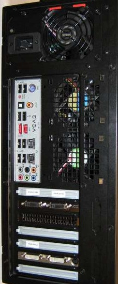
[[File:fig15.png|150px|thumb|right|Figure 15: The rear of the PC]] | [[File:fig15.png|150px|thumb|right|Figure 15: The rear of the PC]] | ||
| − | [[File:fig17.png| | + | [[File:fig17.png|150px|thumb|left|Figure 16: Connections on the rear of the PC.]] |
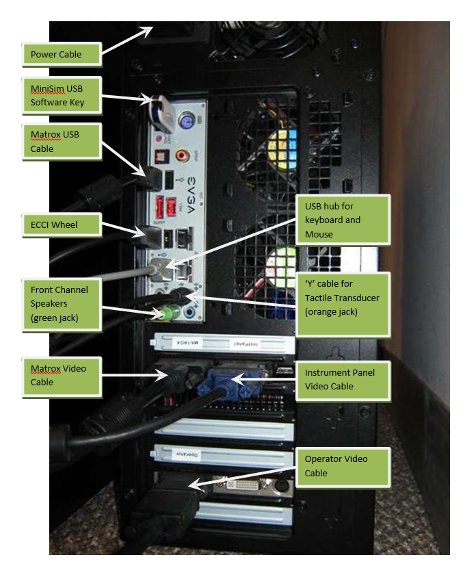
[[File:fig16.png|300px|thumb|right|Figure 16: Connections on the rear of the PC.]] | [[File:fig16.png|300px|thumb|right|Figure 16: Connections on the rear of the PC.]] | ||
Revision as of 15:31, 26 September 2016
Contents
Make the connections
CAUTION! Make ALL connections before powering-up the PC. If the video connections are not made before the PC boots, the desktop and resolution settings will be lost!
When the miniSim is assembled, it is best to make the connections are made in an organized way. This ensures that the system operates as intended the first time and avoids unnecessary troubleshooting, Figure 15.


- Connect the video cables,
- The main video card is where the Matrox and the instrument panel display will be connected. Observe the labels. The Matrox is connected to the port nearest the motherboard,Figure 16.
- The lower video card (9500GT) is for the operator display. The operator display is connected to the port nearest the motherboard, Figure 16.
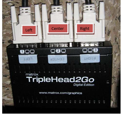
- Connect the video cables from the 3 front channel displays to the Matrox video outputs, Figure 17
- The Matrox Triplehead Adapter has a USB cable – this must be connected to the PC for the Matrox to work properly, Figure 16.
- The USB MiniSim sofwtare key. The software will not run without it, Figure 16.
- Plug the USB extension cable into the HUB and into one of the USB ports on the rear of the PC, Figure 16.
- Connect the 2.1 audio cable to the GREEN audio jack on the rear of the PC, Figure 16.
- Connect the RCA to 1/8” headphone ‘Y’ cable to the ORANGE audio jack on the rear of the PC, Figure 16.
- Connect all the power cords to the power strips.
Power up the PC
Note that the desktop spans all 5 monitors in the system. From left to right, they are Left, Center, right, Instrument Panel, and operator Display. The Icons have been moved so that they appear on the operator display. If they have been re-positioned, it is best to move them now to the operator display. The desktop will look similar to Figure 19 below.
Check the desktop and display configuration
If the computer is booted up after the display(s) have been plugged in to the proper video card output(s), the screen configuration in Windows should remain unchanged and valid. In case the configuration has been altered, and the miniSim visuals channels do not appear to render properly, follow the steps below to reconfigure the screen setup.
- Verify the connections are correct. Review the photos and instructions above. The system uses a Matrox Triple-Head adapter to connect the 3 front channel displays to a single video card output. The Matrox connects to a USB port and to the video card as shown in Error! Reference ource not found. above.
- On the Matrox unit, note that the Left display connects to the output marked ‘1’, the Center connects to the output market ‘2’ and the Right connects to the output marked ‘3’.
- Right-click on the desktop. Choose ‘display resolution’. You should see the following settings. Click ‘Identify’ to see if the order of the displays in the window correspond with the labels below. From left to right, the must be Matrox, Instrument Panel, and Operator Display. It is not important what the actual numbers (1, 2, 3) are, what is important is the order.
- Check the resolution for each channel by clicking on each display icon.
- The Matrox resolution must be set to 3840x1024.
- The instrument panel is usually 1366x768. On some miniSims must be Landscape (flipped).
- The operator display settings are not critical, but should match the display aspect ratio used , 4:3 or 16:9.
- The NVIDIA video card settings should not change, but if they do, typical configuration settings are shown below. Note that the higher the filtering settings, the more the video processor must work – and depending on the visual database used, this may cause jitter or dropped frames. If this happens, try lowering the filtering and gamma correction settings.
Audio configuration
You may need to adjust the PC’s audio configuration if the cabling is changed. Launch the Realtek Audio Manager. The sound system on the MiniSim is a 2.1 Audio, or leaft and right speakers with a subwoofer. You use the Realtek window to specify what jacks are used for what output.
Most applications use the settings similar to the following:
- No special sound processing effects are used
- Front left and right speakers are full range and assigned to the rear green jack
- Subwoofer assigned to the rear orange jack
- Volume set to taste (~95%)
