Route Table
Introduction
The Route Table for the NADS miniSim provides the functionality for forwarding cell data over UDP “datagrams” to a specified location. The datagrams are sent at 60 Hz. The route table configuration is specified by the routeTable.txt file. This file must exist in the “miniSim_install_directory\bin.x64” directory; if the file does not exist the miniSim will operate normally, although no data will be forwarded or recorded.
Structure
The following is an example of a route table:
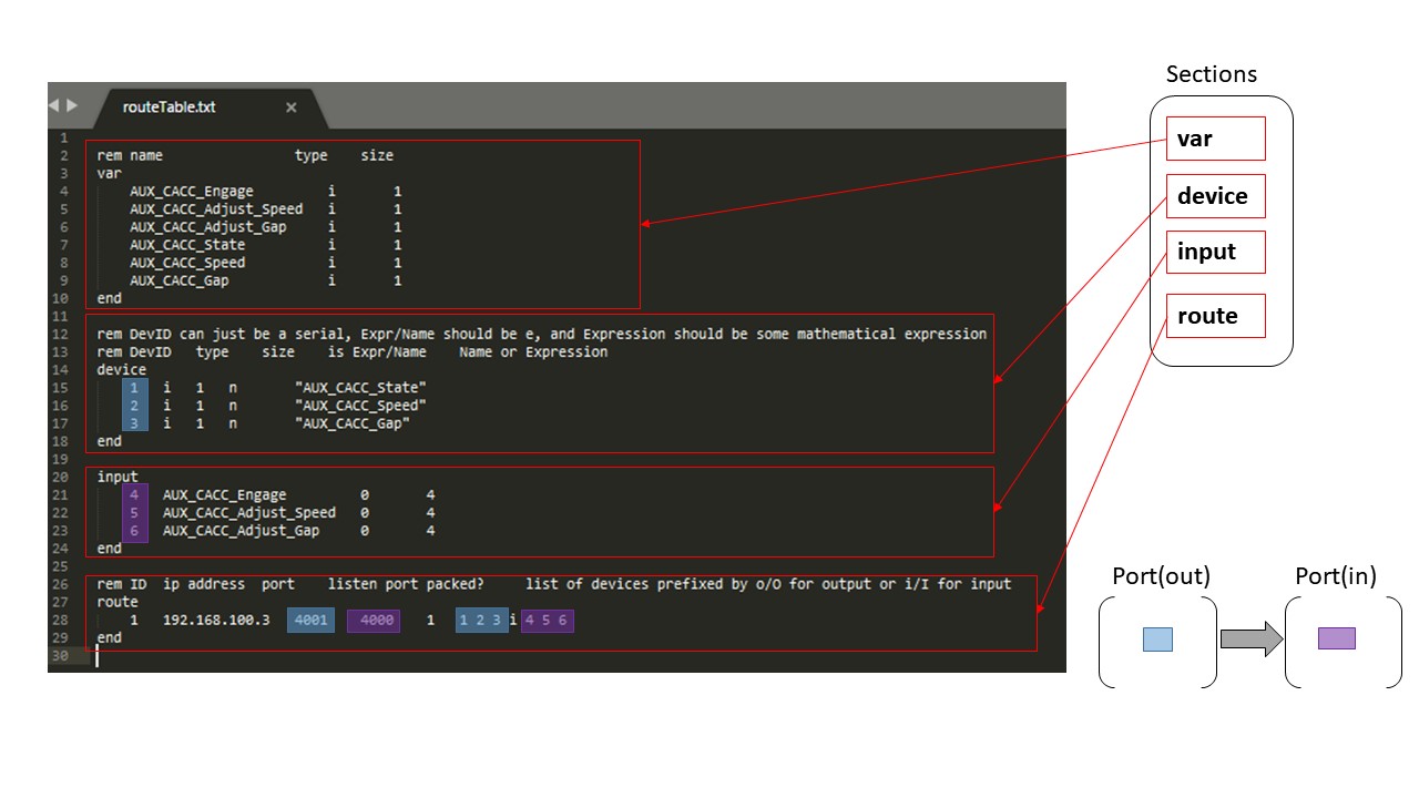 The route table is broken up into 4 sections, the var (L01 to L10), device (L12 to L18), input (L20 to L24) and the route (L26 to L29). Each section must begin with the section name (e.g. see L14 for “device” section), with no other text on the line, and must end with “end” (e.g. see L18 for “device” section) on a line by itself. All lines that begin with “rem” are considered comments and are discarded when the route table is parsed.
Var
<name> <type> <size>
The var section declares a set of variables. Each line in the var section declares one variable. The first thing on the line is the variable name, this must be exactly the same as it appears in the .daq file or the .cec file.
The next item (space or tab delimited) is the type:
'i': 32 bit integer
's': 16 bit short
'f': 32 bit floating point
'd': 64 bit floating point
'c': 8 bit character
The last element on the line is the size, this is the number of elements in the cell, in the above example AUX_CACC_Engage is a single integer.
“FrameNum” is a special variable that does not have to be listed in the cec file, it will provide the current frame number. This is the same frame number that will appear in the daq file.
Device
<id> <type> <size> <e or n> "expression"
The device section is for declaring output varaibles. The first element on the device line, is the id. The id is used in the route section to reference the device. The next element is the type. This uses the same designation as the var section.
The next element is the size, is the element count (currently only 1 is supported).
Next specifies is the output is an expression (e) or just takes the value of a varaible (n).
The last section is the expression. The expression must be in quotes. Each expression must have at least one operator. The so in the above expression the “SCC_Visual_Warning + 0 “, 0 is added to SCC_Visual_Warning as to not change its value. The value of the expression is always evaluated as a double, and then type casted to the type, so vary large integers may get rounded off (double has 52 significant bits), in addition to any rounding that is done to convert the double to the output type.
So in the above example:
1 i 1 n "AUX_CACC_State"
We are taking the 32 bit integer AUX_CACC_State and outputting without any kind of modification.
Input
<id> <varname> <offset> <size>
The input section is for specifying cells the route table is to write to. The cells are written to just as data sent to the miniSim. The first element is the ID, this will be used by the route section. The var, element specifies the varaible name, this cell must exist in the cell table. The offset is in bytes as specifies offset into the cell the data is written. The size specifies how much data in written. If we wanted to write to a cell that was a single integer we would use 0 and 4 for the offset and size.
Route
<id> <ip> <port out> <port in> <packed?> <device1,device2,device3, …>
The route section specifies where to send data. The first element is the id, this needs to be unique for each “route”. The second element is the ip address, followed by the out going communication port and the incoming communication port. The out going port will be used to send data to the target IP address with the given port. The incoming port is the port the miniSim will listen for incoming communications on.
The fifth element (0 or 1) specifies if the data is to be sent in a packed data format or using a NADS specific data protocol (which has not been fully implemented). In general use terms, this should be set to "1".
Next is a list of devices. The devices are specified as above and will appear in the order as they are specified. An “i” serves as the delineation between outputs and inputs. (No "i" character is necessary if there are no inputs required.)
When multiple devices are selected and packed is also specified no padding will appear between variables in the data load.
For the above example the address 192.168.100.3 would be sent a UDP datagram on port 4001 with three 32 bit integers at the rate of 60 Hz. Additionally, the miniSim would also listen locally on port 4000 for a UDP datagram consisting of three 32 bit integers.
Code Examples
Coming soon
