Vehicle Automation
As standard, the miniSim is equipped with two automation functions:
- Lane Following
- This function allows the user to define a ‘path’ for the own-vehicle vehicle during scenario authoring in ISAT, and, when engaged, the own-vehicle will follow this path. Lane Follow can be engaged/disengaged manually by the driver or operator, or via scenario trigger. NBy default, this will disengage when the driver starts steering.
- Enhanced ACC
- This function allows the driver or scenario to set the desired target speed and follow distance. The system will accelerate the own-vehicle from a standstill, and brake it to a stop as in stop and go traffic.
The Vehicle Automation option provides additional support for the following miniSim functions that allow the user to create and test automated vehicle control algorithms.
- Virtual World API
- This is a programmer interface for the miniSim logical road network, or ‘virtual world’. Using this interface, a user’s system can query the scenario determine the location of scenario objects, road and lane locations, and the status of traffic control devices.
- Vehicle Automation Option
- The miniSim team have developed a set of low-level behaviors that can be activated by the scenario, by manual action, or by a user-designed external subsystem. There are also functions for transfer of control, high-level driving style parameters, and support for existing scenario control triggering systems.
- User-Defined Simulator Subsystem
- The minSim supports linking to user-defined subsystems. The ability to link user developed functions to the subsystem has many applications, including the incorporation of active vehicle safety systems or automation functions into the miniSim driver in the loop simulation environment.
Contents
Logical Database API
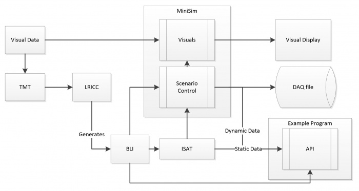
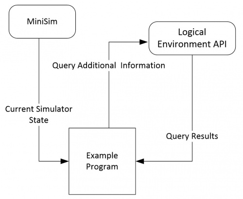
This Logical Database API is to provide a simplified programmer interface into CVED, to serve as a method to extract road information at run time on the miniSim. This API will not directly serve as an interface into the miniSim, it will however be able to open the BLI file and run parallel with the miniSim. As part of the delivery an example program that does provide a communication interface to the miniSim, and utilizes this API will be delivered. The below figure shows the data-flow, where the example program receives the current state information including the position of the driver, the example program then uses this information to query the API.
Definitions:
| CVED | Correlated Virtual Environment Database is an API used internally to read the bli, and query the road network. |
| BLI | Binary Logical road Interface, this is a file that contains all of the logical road information. |
| SOL | The sol file provides static information about static or dynamic objects, such as the bounding box size. |
| Corridor | A corridor is a defined path through an intersection. |
| Static Object | Static objects include signs, and non-moving objects that are either part of the BLI, or inserted into ISAT by the scenario author. |
| Dynamic Object | Dynamic objects are those objects that when created by running the scenario, have a physical presence in the simulation, and are updated by scenario control. These are either ADOs or DDOs. |
The API is developed in C++; it will be delivered as a library file built in VS 2010, with a header files. The API is object oriented in design and will use Hungarian notation (classes begin with C, member variable will begin with m_). The example program will be provided as a source code distribution, with a project and solution file for VS 2010. This program will be developed with C++. The operation of the example program will require network connectivity with the miniSim. The API will require in the installation directory of the executable:
- a copy of the BLI
- a copy of the SOL file
- a copy of the scenario file
Description of API Functionality
The API provides an interface that will allow a user to query logical information about the driving environment, such as lane width, distance to next intersection. The API will accept x,y,z locations and provide road related data about said location. This shall have real-time level performance. It also shall be possible to use this API in a system that is not directly connected to the miniSim.
The example program will communicate with the miniSim, and will utilize at least one version of every API available, duplicate calls that only vary in call type (i.e. float vs. double) may only have 1 version called. This program will provided as an example of the API, and will provide validation of the API.
Road Information
The API will provide a series of functions that allow the user to input an X,Y,Z location and get logical information at that location, including lane width, road marking type , surface type . Only a minority of tiles have tags (or attributes) that allow road marking information to be queried by CVED, hence this API will only provide road marking information from BLIs that a marked with tags for road markings. Should a road position not have valid markings tag, a return code will indicate no information was available.
- GetLaneWidth()
- This will return the current width of the current lane at a given XYZ location.
- GetRoadMarkings()
- This will return lane marking type, on the right and left of the lane. This shall also provide distance from center line to inside of lane markings at a given XYZ location.
- GetLaneLayout()
- This function shall return the number of lanes, the direction of each lane, and meta-data about the lane, given a XYZ position; this will not function in intersection.
- GetLaneSurfaceType()
- This function will return the road surface type at the current location. Documentation will be provided as to what the surface type codes indicate.
- GetRoadTrace()
- This function will take the current position, and a distance, and return an array of x,y,z points and lane width, following road. A version of this function will use the driver’s path as specified by the scenario, and use that to navigate any intersections that the function may encounter. Another form of the function will take a direction in, and will navigate the intersection using a given direction (right, left, straight). Another version will take a corridor id, and provide a trace through the corridor.
- GetOncomingIntersection()
- Forms of this function will return: the distance to the next intersection 0, if currently located on an intersection, and list of connected corridors, and their respective turn directions.
- GetOncomingHaltLine()
- This function will return the distance and x,y,z, location of the next oncoming halt line, version of this function will take the drivers path to determine what halt line to stop at.
- GetOncomingMergePoints()
- This function will take a distance, and position, it will project forward, and return distances to, and x,y,z location for points where two corridors begin to overlap.
- GetLightState()
- This function will take in location information and the traffic light state data past from the miniSim, and will indicate what the traffic light state is for said location.
- GetCurvature()
- This function will take xyz location, and return the radius of curvature for said location.
- GetGrade()
- Given an x,y,z get the road grade of the road in degrees.
- ChangeLanes()
- Given a position (XYZ) on a road segment (not in an intersection) and a lane offset(+ meaning lanes to the right, negative numbers mean to the left, this function will return center of the lane indicated by the lane offset or an error code indicating why it cannot changes lanes( i.e. the lane does not exist, or is an oncoming lane).
Static Object Functions
- GetStaticObjects()
- Given a bounding box, this function will return a list of static objects, this will include x,y,z information and sol ID. Most signs will provide a x,y,z location, where this position will provide the bottom of the post of the sign (for signs with a single post). The height of the sign will be derivable from the GetSolInfo. However not every sign‘s position is directly related to its position in the BLI (some signs such as interstate with many components do not match the actual position as to ease authoring and viewing the sign in ISAT). Some guidance will be provided as what signs can have their positions directly derived from the bli.
Dynamic Object Functions
- UpdateDynamicObjects()
- This function takes in the dynamic object data outputted from the miniSim, and adds entries into CVED for each object.
- GetDynamicObjects()
- Given a bounding box, this function will return a list of dynamic objects, this will include x,y,z information and sol ID.
- GetTerrainObjects()
- Given a bounding box, this function will return a list of terrain objects; terrain objects provide information about the location of additional terrain information, such as parking lots, or buildings. This tends to only be a much smaller subset of what is in the visual database, this API will only allow access to terrain objects that have been placed in the BLI file.
- GetSolInfo ()
- Given sol ID (that which is part of the dynamic object data), this function will return information from the SOL file, including the minimum bounding box for the object.
Example program
An example program is provided. This program:
- Utilizes every query available to the API
- Every query function accessible to the API shall be called at least one
- MiniSim Connectivity
- The sample program shall receive all data that the query API may utilize, and properly load the data into the API’s objects.
- Full Source code and project file will be provided
- The source code and project files will be provided for the sample program, the end user shall be able to build this program using Visual Studio 2010
Vehicle Automation Option
The miniSim team have developed a set of low-level behaviors that can be activated by the scenario, by manual action, or by a user-designed external subsystem. There are also functions for transfer of control, high-level driving style parameters, and support for existing scenario control triggering systems. Along with the logical database API, it provides the user with the tools to develop their own high-level systems for executive control. The functions are as follows (excerpted from the development document):
Lane Following
A low-level controller has been implemented to allow the ownship vehicle to following the lane in which it is traveling. The controller works over a range of speeds from urban to highway driving, and is able to work on curved roads. The controller does not manage changing lanes, making turns, etc. These functions are covered in new functions described below. The control system that has been implemented in Simulink shall be integrated into the miniSim software.
Speed Following
An adaptive cruise control (ACC) system has been implemented in vehicle dynamics. This system was designed for an ACC study and modeled after a Toyota Avalon tested at that time. There is a deceleration limit on the ACC authority; and the system does not work below 25 mph or respond to objects that are moving less than about 5mph. This system shall be enhanced/modified as needed to work smoothly with the other automated functions.
Lane Change
A lane change maneuver shall be implemented that is distinct from turns and exits, such that it may occur on any section of roadway, including curved roads. The lane change may occur to the left or to the right, but shall not intrude into an oncoming lane, and thus shall not accommodate some passing maneuvers. The lane change maneuver shall be incorporated into high level control logic as needed to accommodate other maneuvers. For example, a left turn may be specified that would require a lane change into a left turn lane. The system shall be able to recognize this and request a lane change preceding the left turn.
Brake to Stop
Most intersections have stop lines at which vehicles are expected to stop in the presence of a stop sign or a red light. The automation controller shall recognize stop lines and be able to bring the vehicle to a complete stop at such locations. The ability to cause the ownship vehicle to brake to a stop at an arbitrary location shall also be provided. This function may be used to simulate a system failure or some other experimental manipulation. The high level logic around this maneuver shall not, at this time, recognize the presence of stop signs or the state of traffic signals; however, that capability may be added at a later time.
Merge / Exit
The ownship vehicle shall be able to autonomously merge onto highways and exit off them. The controller in these situations shall be able to accommodate the interchange types most often encountered in miniSim databases (ex: overpasses and cloverleafs). If there is a choice of turn direction after exiting a highway, then the operator must specify a turn as they normally would at any other intersection.
Turning
The automation shall be able to make the ownship vehicle turn left or right at an intersection, whether that intersection is a 4-way, 3-way, or Y intersection. Two variations of turning shall be provided. The first is a stop, turn, go maneuver in which the vehicle comes to a complete stop before proceeding. The second is a slow, turn, go maneuver in which the vehicle rolls into the intersection and navigates through it at a comfortable speed. If there is a choice of destination lanes, then the controller shall choose the rightmost lane on a right turn and the leftmost lane on a left turn.
Pull Over
The automation shall be able to make the ownship pull over to the shoulder or curb of the road to a stop. The purpose of this behavior is to provide an acceptable ‘default’ behavior in cases where the driver is disabled or unable to act.
Abort
The automation shall allow the occupant to abort an action and revert to the previous valid action. For example, if the car is attempting a lane change and the passenger wishes to abort, the car will remain doing the last valid behavior (in this case, lane following).
Transfer of Control
Mechanisms shall be provided to allow the driver to transfer control to the automation as well as take back control from it. A driver interface shall be provided in some form to notify the driver of the current state of the automation. The operator shall be able to specify a total or partial transfer of control, where partial refers to transferring one axis of control while leaving the other in its current state. Transfer from the automated to manual control shall be able to be triggered by the operator to simulate a system failure of some kind.
Driving Style
The automation controllers shall be able to perform all the maneuvers described above in a consistent manner, similar to how a human driver would perform them. Moreover, the operator (and perhaps the driver) shall be able to set the driving style from among a limited set of options ranging from more conservative to more aggressive, in order to better match driver’s preferences.
Triggers
The operator shall be able to issue ‘turn-by-turn’ instructions to the automation in order to simulate an automated route navigation feature. If the route is fixed and pre-determined, then these instructions may be embedded in the scenario as triggered behaviors. However, they may also be issued manually by the operator as the drive is progressing. For example, if the operator issues a command to turn right, it shall be understood by the navigation controller that a right turn is requested at the next available opportunity. An operator interface of some kind shall be provided to allow the operator to interact with the navigation controller.
User-Defined Simulator Subsystem
The miniSim subsystems are state machines, whose current states are controlled through the user interface. A user can create a custom subsystem to run with the rest of the miniSim simulator. The ability to link user developed functions to the subsystem has many applications, including the incorporation of active vehicle safety systems or automation functions into the miniSim driver in the loop simulation environment. It is also possible to build custom MatLab functions into static library files, include their accompanying C++ header files in the source code for the custom subsystem, and link the static libraries into the project the same way the libraries for the subsystem base class are linked in. Custom subsystems can be added to the miniSim with little change to the rest parts of the system. The custom subsystem can be built from the subsystem base class which provides an inter-subsystem data communication interface and the functionalities of the real-time scheduling core that monitors state changes. The user layer registers input and output data elements, and executes custom functions that based on the current state of the simulator, interpret the input data and generate outputs. The miniSim team will provide code for a functioning example subsystem. Included in the package are the required header and library files to write the code for a subsystem, as well the sample source code for a simple subsystem which does data input and output via the element registration scheme and handles state changes. The miniSim software was written in C++ and built with Microsoft Visual Studio.Net solution and project files for the sample subsystem are included.


