Visual Trigger Representation
ISAT User's Guide Table of Contents
Contents
Visual Trigger Representation
The visual representation of triggers has been designed to convey as much information about the trigger as possible without forcing the user to bring up the Properties dialog box to review the trigger's functionality. Unfortunately, given the amount of information associated with triggers, it is not possible to visually display all of it. Therefore, the current design focuses on a certain subset of all available information.
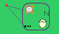
Figure 9-78 illustrates a typical representation of a trigger. A small red circle identifies the actual location of the trigger. This is the location used for Creation Radius calculations. A separate box with rounded corners is used to depict key parameters associated with the trigger. Two lines help associate the pictorial representation of the trigger with its home location. The pictorial representation can be dragged with the mouse to any location without moving the home location. This allows the pictorial representation to be spread so it does not occlude other scenario elements or other triggers.
The pictorial trigger representation is divided into several areas, each containing smaller iconic indicators of the trigger's parameters. Figure 9-79 illustrates these areas and their meanings.
TOP The trigger type icon reflects the predicate used by the trigger. Figure 9-80 illustrates all trigger types side by side. Depicted from left to right are the global time trigger, road pad trigger, time to arrival trigger, traffic light trigger, and geometrical position trigger.
The Action Cardinality area in Figure 9-79 provides a simple indication of the number of actions involved in the trigger. A single dot indicates a sole action, whereas multiple dots indicate multiple actions.
The Trigger Action icon pictorially represents the first action associated with the trigger. There is a distinct icon for each available trigger action; however, only the first action is depicted. If many actions are defined, the user has to use the dialog box to review the remaining actions. The Action Cardinality indicator can be useful in determining if actions other than the one depicted by the trigger action icon are defined. Figure 9-81 illustrates all iconic representations of the trigger actions. Depicted from left to right and top to bottom are the Create Element, Delete Element, Press Button, Set Dial, Select Traffic Manager Set, Play Audio, Vehicle Failure, Set Traffic Light, Log Data, Terminate Simulation, Pre-position Motion Base, Tune Motion Base, and Initiate Phone Call actions.
Finally, the target set area provides an iconic representation of how the trigger's target set is determined. The precise iconic representation is currently under development, and an initial method of using the first letter of the set is utilized (e.g., T for type, N for name, etc.).
Using Triggers to build Scenario Events
Triggers are the building blocks of most scenario events. This section provides some guidelines and examples of how triggers can be used, with emphasis on the intended usage of each trigger. Keep in mind that the guidelines provided here should not be considered as a limitation. They are merely suggestions for how to use triggers. Finding new and innovative ways to use triggers is encouraged.
Triggers generally have low computational overhead, so they can be used freely within reason. However, when the number of triggers in a scenario exceeds one hundred or so, some care should be taken to control the computational load. The easiest way to do this is by using the Creation Radius parameter to activate a trigger only when a driver gets near.
The actual placement of the trigger is not important other than affecting when the trigger is activated when the Creation Radius is specified. Therefore, place the trigger near the region where it will be affecting things, but not on the road network where it can hide other scenario elements.
Carefully evaluate the need of either defining a trigger as a one-shot trigger or specifying a non- zero denounce value. Several triggers will fire continuously after their predicate is satisfied. For example, with a zero denounce value, the global time trigger will fire continuously once the specified time has been reached. This can be problematic if its action is to create an ADO. At the scenario control system’s default execution rate of 30 Hz, such a trigger will create 300 new objects in 10 seconds. This is guaranteed to overload not only the scenario control system, but also the Image Generator, the real-time communication channels, and a variety of other subsystems. The simulation will ultimately halt because of the overload.
The intended usage of certain trigger actions should be very clear. For example, the Terminate Simulation action can be used to deterministic stop the simulation either when the driver reaches a particular point or after a fixed amount of time. Therefore, a global time trigger whose action is to terminate the simulation provides a convenient way to ensure that all subjects in an experiment drive for exactly the same time. Other actions are much more flexible. For example, setting the dial of a traffic element is a powerful way to modify the behavior of traffic. When using such actions, it is critical to use the ISAT’s rehearsal mode to verify that the actual behavior is what was intended.
TOP When using actions that affect other scenario elements, the selection of the Target Set (i.e., the scenario elements that will be affected by the trigger) is critical. There are several ways to select the Target Set, each with its own advantages and disadvantages. In addition, multiple constraints can be used to define the Target Set. When multiple constraints are specified, they must all be satisfied for a scenario element to make it in the final Target Set. In other words, the constraints are combined with a Boolean AND operation. Further considerations for each constraint are given below:
- Using the name of a scenario element is convenient; however, keep in mind that uniqueness of names is not enforced within the scenario control system. As a result, this type of selection is best used when the intended target is created by means other than the traffic manager. For example, forcing an ADO to run a red light can be done by creating the ADO with a specific name that the user ensures is unique, then using a trigger whose Target Set is by name.
- Using the type of a scenario element usually makes sense in combination with another constraint, such as geometric position. An example of using the type as a constraint would be to place a trigger that, when it fires, dictates that all trucks on a given area should take the next exit. The type and geometric position would be used, along with an action that presses the Turn Right button on the selected scenario elements.
- The road position constraint allows selection of any number of lanes so that all elements traveling on these lanes would be included in the target set. Combined with the type or name constraints, this provides a very powerful mechanism for selecting objects.
- The geometric position trigger is similar to the road position, but it uses a geometric shape that can be used “off-road”. Use it to select pedestrians or rail vehicles.
- The Instigator Set indicates that the trigger will affect the same objects that caused the trigger to fire. A simple example of using it is in defining a traffic sink (i.e., a place in the road network that deletes any scenario element that travels there). To implement this, select the action "Delete" with the Target Set specified as Instigator Set. Another issue to consider when using the Instigator Set is that various triggers provide additional flexibility in defining the Instigator Set. For example, a road pad trigger may fire because three vehicles stepped on the pad simultaneously. Alternatively, a trigger may have an activation delay so that by the time the trigger is activated, there are numerous vehicles on its pad. All such vehicles would belong to the Instigator Set unless the trigger parameters specified in the Specific tab in the Trigger dialog box further trim the Instigator Set.
TOP Finally, try to utilize the triggers’ ability to have multiple actions associated with them. A scenario will execute faster and be easier to understand if it uses fewer triggers that do more things, as opposed to numerous triggers that have the same predicate but do different things.
Verification Tool
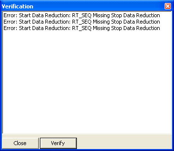
Misuse of triggers is one of the biggest causes of scenario authoring errors; these errors include creating stop or start data reduction without a stop, missing predicate information, missing action information and many other errors. The verification tool was introduced in order to help catch these errors. The verification tool is launched by clicking on (the Red check) icon on the view toolbar. This tool will not find all possible errors, it is meant to help catch simple authoring errors.
Click the verify button to refresh the error list. Click on the error description will set the focus on the scenario element in question. The verification tool is run when the .scn is saved, if an error is found the verification window is opened. This can be disabled by going to the Edit->Preferences->Verify and unchecking the check at start option.
Data Reduction Graph
The data reduction graph is a new tool that has been introduced in ISAT version 1.5, which is meant visualize data reductions. One problem with data reductions is that there is no way for ISAT to automatically tell if for a given event all the possible start and stops of the event have a stop or start data reduction action. For instance if we have an event where the car suddenly stops in front of the participant, and we are trying to comprehend their reaction time, we need to have a stop reduction for each possible case the driver could avoid the accident, such as either stopping, or swerving to avoid the accident.
The reduction graph has two views, “By Reduction”, and “By Action”. The “By Reduction” view organizes the chart by each reduction, that which is identified by actions that have the same group number, variable type and column name. Since each action can have multiple variables, a specific action may appear in multiple under multiple reductions. The “By Action” view organizes the view by action. It draws a line from each stop reduction action to the start reduction action that it is stopping. When an action block is clicked on, ISAT will set the view to the trigger that contains the given action
[[File: DataRedutionGraph.png |600px|thumb|center|Figure 9-83 Data Reduction Graph]
Reusing Scenario Components


