BEHAVIOR II
ISAT User's Guide Table of Contents
Contents
Authoring Virtual Objects
Behavior
Virtual Objects are objects that can be placed in the virtual environment, and only have a visual representation. An Icon flashing on the screen would be an example of a “virtual object.” Each virtual object must be given a unique name. There are two different render types for virtual objects, In Scene and Overlay. Overlay objects will not interact with the contents of the virtual environment; these will be displayed with an Orthogonal projection, meaning they will not change size or shape, based on location. In scene objects are inserted into the virtual environment and use a 3D projection, so the farther away they are from the driver the smaller they will be, they can also be obstructed by other objects, such as an oncoming car. Currently, In Scene objects can only be attached to the ownership vehicle. As a part of the virtual environment, In Scene objects can be visually obscured by other objects in the scene.
Authoring Virtual Objects
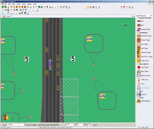
To create a new Virtual Object, select the menu option and Insert->Virtual Object Or click and drag the Virtual Object from the “Isat Elements” toolbar
The cursor will turn into the insertion cursor:
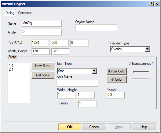
Now left click on the map where you would like you place your Virtual Object. Once you have placed the Virtual Object, the properties dialog will appear. There are two tabs: Dialog and Comment. The Dialog tab allows you to set all of the properties of the object. By default the name of the Virtual Object is VirtObj, which must be changed to a unique name. The functionality of the remaining fields is described below.
Setting Virtual Object position and size
Setting the position and size of the Virtual Object is dependent on the type of the Virtual Object. Overlay objects use PIXELS as units, and In Scene objects use FEET as units, and angle is always in degrees.
For Overlay Objects, the position is set ( in x,y, ) from the BOTTOM CENTER of the display. Positive X is the number of pixels to the right of the center, Negative X is to the left of the center; Positive Y is the only meaningful Y value here, and it is the number of pixels above the bottom of the display. Width and Height are also set in pixels. Rotation angle is set in degrees, a positive angle rotates the object counterclockwise, and a negative angle rotates the object clockwise
For In Scene Objects, the position is set ( in x, y, z ) relative to the bottom center of the ownership vehicle. The coordinate system is as follows, as viewing from the driver: +x is to the right, +y is forward, and +z is up. The origin of the coordinate system is the BOTTOM center of the ownership vehicle, so if you wanted something to be at eye-level with the driver, you would have to give it a positive z value, as well as a positive y value to bring it out in front of the driver. Units for position and size are in feet, and units for angle are in degrees.
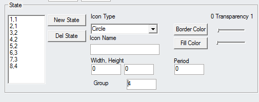
Specifying the stat and using the state table for animation
The bottom half of the Dialog tab is for setting the states of the Object. These states can be used to animate the Virtual Object, or to set a static type object with one state.
The Icon type has different shapes to choose from, as well as an “Icon” option. To use the Icon option, you must enter the filename of the desired Icon in the “Icon Name” field, including the extension; otherwise it can be left blank. To insert a blank frame, you can set “Icon Type” to Icon, and set “Icon Name” to NULL. In the left column there are two numbers separated by a comma, the first number is the state, and the second number is the group. The group number is used to differentiate between animations, and the states are used to differentiate between states within that animation. The group is 1 by default, and a group 0 is reserved for OFF. You can trigger the animation to begin, with a Set Dial->Virtual Object->SetStateIndex action, which is described below. For each state within the group, you can set the Size, Color, and Period. Size is set using the “Width” and “Height” fields. Unlike the same fields above, these “Width” and “Height” fields are scalars of the original size. The period is the duration that the object will remain in that state; the Color has two fields. The Border Color is the color of the border of the shape, and the Fill Color is everything within the border. There is also a Transparency slider for each Color, with 0 being transparent and 1 being completely visible.
Adding Icons
To add an icon to be used as a virtual object, place it in the following directory in your MiniSim install:
\data\Visuals\Models\ModelTx Ex. C:\NadsMiniSim_1.8.3.3\data\Visuals\Models\ModelTx
Triggering Virtual Objects
Virtual Objects can be modified/moved/animated using any of the available triggers. Virtual Objects can be modified by with a Set Dial->Virtual Object-> action
600px|thumb|center|Figure 1-6 Set Virtual Object Dial
Setting Virtual Object Dials
There are seven different dials: SetAnimation, SetRotation, SetPosition, SetColor, SerBorderColor, SetSize, and SetStateIndex.
SetAnimation
This will take in a string and animate the desired Virtual Object according to the string. The format of the input string is as follows :
rotate [degrees per second] ; move [X] [Y] [Z] [rate]
This will rotate the object at the specified rate, as well as move it to the desired position at the specified rate. The movement rate is in units per second, and the object will stop moving once it has reached the specified XYZ. The units and coordinate system are based on the type of Visual Object as described above, with Overlay objects in pixels, and In Scene objects in feet.
SetRotation
Similar to the first part of the SetAnimation dial, SetRotation takes in a string and will rotate the Visual Object at a specified rate. Format is as follows :
rotate [degrees per second]
SetPosition
This will move the Visual Object to the specified position, XY for Overlay objects, XYZ for In scene objects. The units and coordinate system are based on the type of Visual Object as described above.
TOP
SetColor
This takes in 4 floats, separated by a semi-colon. The first three floats are the values of Red, Green, and Blue, respectively; The last value is the Alpha, or transparency, value. 1 is transparent, and 0 is completely visible.
TOP SetBorderColor
Similar to SetColor, This takes in 4 floats, separated by a semi-colon. The first three floats are the values of Red, Green, and Blue, respectively; The last value is the Alpha, or transparency, value. 1 is transparent, and 0 is completely visible.
TOP SetSize
This takes in two ints to set the height and width of the object. The units are based on the type of Visual Object as described above.
TOP SetStateIndex
This is used to set the state of the Visual Object, and takes in the group number of an object. The default state for OFF is 0. This can be used to start an animation that you have previously authored in the Dialog tab, in the Object settings as described above.


