Traffic Source
ISAT User's Guide Table of Contents
Contents
Traffic Source
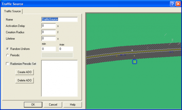
Traffic sources are used to create traffic at a specific point. These coordinators are useful for creating ambient traffic. This can save time over inserting a large number of ADOs and DDOs to create this effect manually. This can also be useful for creating traffic at intersections. They can be created by triggers as well. The traffic source is denoted by the icon. A traffic source creates ADOs or DDOs at either a random interval or one that is specified by the user. The traffic source will only create one at a time. The traffic object will be created at the location specified by the user, if traffic source has more then one creation location, the actual location will be determined randomly at runtime.
In order to place a traffic element to be created, click on either the ADO or the DDO button. This will allow you to place either a ADO or DDO in the mini-ISAT view in the dialog. Once placed these scenario element can be moved to any location. They will not exist as regular scenario elements but rather points in which said scenario element might be created by the source at run time. The “Random Uniform” option allows the user to select a random uniform distribution for the time interval between traffic element creations. The min and max edit boxes specify the minimum and maximum time intervals for the random distribution. The periodic option specifies a set of intervals the traffic elements will be created. Such as if 12,3,4 was entered into the periodic edit box, a traffic element would be created at 12 seconds, then 3 seconds latter and then at a 4 second interval after that. The “randomize periodic set” option will randomly shuffle the order the periodic delays. So this option might for create the elements at a interval of 12,4,3, and then at intervals of 3,12,4. Every time a set is run through, it is then reshuffled.
The Traffic Light Manager
Behavior
The Traffic Light Manager (TLM) is responsible for controlling the sequencing of traffic lights in the virtual environment. Note that by default, traffic lights are set to the off state. The TLM must be activated, and timing should be defined for all intersections whose traffic lights need to be operating during the simulation.
Timing is defined for groups of related traffic lights. These groups are called Coordinate Light Groups (CLGs). Currently the grouping of lights into CLGs is done automatically by the software that generates the road network; it cannot be modified by the user. In general, all traffic lights on an intersection are grouped together in a CLG.
Within each CLG, timing is specified by providing an arbitrary number of states and then explicitly specifying the color of each traffic light during that state. The duration of each state is also specified. At runtime, the TLM implements a simple state machine that visits all states in the order they were specified. At each state transition, the TLM modifies the color of the traffic lights in the scene to represent the color specified in the timing table.
In general, the TLM utilizes a small, but not negligible, part of the computing capacity of the scenario computer. However, when the number of traffic lights is very large, the I/O time necessary to communicate the state of each traffic light to the IG can be quite large. As a result, the TLM provides the ability to load balance the system by only operating traffic lights that are within a certain range of the simulator driver. Use of this load balancing is almost mandatory when a scene contains more than approximately one hundred traffic lights.
Defining Traffic Light Timing
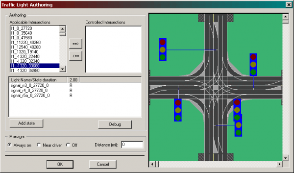
Following are the steps for specifying the parameters of the TLM. The TLM can be accessed through Insert->Global Scenario Elements->Coordinators->Traffic Light Manager Menu. Alternatively, click the appropriate toolbar button. A dialog box similar to the one shown in Figure 8-60 appears.
Overview
The dialog box is divided in two major areas: the work area on the left and the view area on the right. The work area is further divided into the authoring area and the manager area. The authoring area allows authoring of the timing table of CLGs, and the manager area allows specification of parameters associated with the TLM.
The following steps are involved in the specification of the traffic light timing tables. First, the intersections whose traffic lights will be controlled are selected. Then, for each of the controlled intersections, the number of states is specified. Finally, the color that each traffic light will have during each state is specified.
Selecting controlled intersections
As described earlier, intersections are used to group traffic lights into CLGs. Thus, in this section, any reference to an intersection is equivalent to a single CLG containing all traffic lights associated with that intersection.
The Applicable Intersections list box contains all intersections in the scene. The actual names are derived though an automated process that does not necessarily yield any useful naming. However, selecting any of the names in the list box will force the view area to center and zoom the display on the selected intersection. For example, the intersection displayed on the view area in Figure 8-60 is named I1_-1320_33660. While an intersection's name is selected on the Applicable Intersections list, clicking on the <- button will move it to the Controlled Intersection list. Similarly, clicking on the ->button will move any selected intersection from the Controlled Intersection list back to the Applicable Intersections list. Only the timing for traffic lights belonging to intersections listed in the Controlled Intersections list can be specified.
Authoring traffic light states
To define the traffic light timing for an intersection appearing in the Controlled Intersection list, first click on the intersection name in that list. Note that the view on the right centers and zooms to the specified intersection. At the same time, the list on the lower part of the Authoring box is updated to reflect all traffic lights in the intersection. Selecting any of the traffic lights in the lower part highlights that traffic light on the view.
The list on the bottom part of the Authoring box initially contains two columns (see Figure 8-60). The left-most column always contains a list of the traffic lights in the selected intersection. Each of the remaining columns to the right represents a state in the timing table. The title of the column indicates the duration of the state in seconds. The contents of that column are the colors of the respective traffic lights while the state represented by the column is active.
To add a new state, click on Add state. A new column will appear in the timing table list. The initial duration of each new state is two seconds, and the color of all traffic lights is set to red.
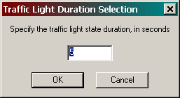
To change the duration of a state, right-click on the title of the column and select Edit state duration from the pop-up menu. The dialog box shown in Figure 8-61 appears.
Type the desired state duration and click OK or press Enter. The dialog box disappears and the updated state duration appears on the column heading.
To change the color of a traffic light, right-click on the letter representing the color. A pop-up menu containing all possible traffic light colors appears. Select the desired color. Once the pop-up menu disappears, the table will be updated with the new color.
Figure 8-62 shows the timing table list after two states have been defined, in addition to the state that appears by default. The duration of the first state is 2.0 seconds, the duration of the second state is 4.3 seconds, and the duration of the third state is 5.5 seconds. For the duration of the last state, the first light will be green, the second light will be yellow, the third light will be red, and the last light will be flashing yellow.
In the above example, the duration of the whole cycle will be 11.8 seconds. The second traffic light, named signal_r1_-1320_34980_180, will be red for the first two seconds, and then will switch to flashing green for 4.3 seconds; next, it will switch to yellow for 5.5 seconds, and will switch back to red for 2.0 seconds, and so on.
To delete a state, right-click on the heading of the column representing the state to be deleted, and then a pop-up menu should appear, then click Delete state.
Load Management
This section of the Manager Dialog box allows specification of parameters that help balance the I/O load on the host to IG channel, a significant percentage of which can be consumed by continuously transferring the state of hundreds or thousands of traffic lights. In general, there are two ways to reduce the load. The first method is to limit the number of intersections in the Controlled Intersections list to only those that the simulator driver is expected to drive through or near. The second method is by limiting which intersections the TLM will communicate to the IG based on the distance between the simulator driver and the intersection.
When Always on is selected in the Manager section of the dialog box, all intersections in the Controlled Intersections list will be included in the traffic light simulation and communicated to the IG, independent of the distance to the driver. When Near driver is selected, only traffic lights in intersections whose centroid is within the distance specified in the Distance list are simulated and communicated to the IG.
Finally, when "Off" is selected, the TLM is inactive.
Using the TLM in Authoring Scenario Events=
The TLM's involvement in the development of a scenario event can be passive or active. Passive involvement refers to activating the TLM to increase the fidelity of the scenario and the realism of the overall experience, but without having any forced interaction with the traffic lights. Active involvement refers to having the state or state change of one or more traffic lights as an integral part of a scenario event.
Two methods allow synchronization of traffic lights with specific events in the virtual environment. The first method involves the use of a trigger that uses traffic light state changes as a condition for firing. The second method, which applies to all triggers, involves setting the trigger's action to that of forcing a particular traffic light into a specific state (Force_State) within a given amount of time (Force_Time). The first method depends only on monitoring the state of the traffic lights and does not affect the TLM. The second method, however, modifies the operation of the TLM as follows. When a traffic light is forced to a specific state, the TLM computes the time between the current instance and when the traffic light would reach the Force_State. If the calculated time is the same as the Force_Time, then no action takes place. If the calculated time is different than Force_Time, the TLM scales the time step applied to the evolution of all lights in the CLG so that the Force_State will be reached in exactly Force_Time seconds. This approach ensures that the CLG remains consistent, in the sense that two intersecting roads will not both give a green light. For example, consider the timing table shown in Figure 8-62. Let us assume that due to the firing of a trigger, the second traffic light is forced to yellow within one second. For the purposes of this example, let us further assume that the time that the trigger fires, the current time, is one second into the first state. The time between the firing event and the natural arrival of the forced state would have been 5.3 seconds (1 second remaining on the first state and 4.3 on the second state). Because the forced time is set to 1 second, the whole evolution of this state table will be accelerated so that all lights will turn into the colors of state 2 within 0.188 seconds and into the colors of state 3 within 0.811 seconds after switching into state 2. Once the Force_State is reached, the TLM will continue the simulation using normally scaled transitions. One final note regarding timing: Because the overall scenario control system is simulated at a finite time step (currently a 33.3 millisecond time step), any time specification that depends on a resolution higher than the time step is likely to operate in a somewhat random manner.


