FAQ
Contents
- 1 miniSim Data Dictionary
- 2 miniSim Documentation
- 3 miniSim Hardware
- 3.1 Desktop and Viewport Settings
- 3.2 Q: My miniSim displays have changed. What happened, and how can I fix it?
- 3.3 Q: What is the right Channel Configuration File for my miniSim?
- 3.4 Q: Where do I find data relating to the brake pedal force/position?
- 3.5 Q: How can I adjust the brake pedal response?
- 3.6 Q: The tactile transducer, mounted under the cab, suddenly does not respond when the miniSim is running.
- 4 miniSim Operation
- 5 miniSim Software
- 6 ISAT/Scenario
- 6.1 New to ISAT?
- 6.2 Data Logging: miniSim Default Measures
- 6.3 Q: How do we make an ADO or DDO go backward?
- 6.4 Q: How do I play a sound in my scenario?
- 6.5 Q: How do I add a trigger to my scenario?
- 6.6 Q: What is a “Write to Cell” action?
- 6.7 Q: How can I tell if the driver has left the road?
- 6.8 Q: How can I tell what surface the driver is driving over?
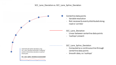
- 6.9 Q: What is the difference between SCC_Lane_Deviation and SCC_Lane_Spline_Deviation?
miniSim Data Dictionary
The data dictionary is a compilation of the simulator data that is stored and available within the DAQ file after each drive.
File:Cells-miniSim-20240715.pdf
Note: miniSim users may extend the data dictionary by adding custom cells to the collect and schedule files:
- NadsMiniSim_x.x\data\NadsMiniSimCollect.general.txt
- NadsMiniSim_x.x\data\NadsMiniSim.cec
Typically new cells should be added into one of the SCNVIF sections. Use the same SCNVIF section for both files:
- cell 1 SCNVIF
- cell 7 SCNVIF
- cell 8 SCNVIF
- cell 9 SCNVIF
miniSim Documentation
All miniSim simulators ship with a documentation folder located on the desktop. You can find miniSim and additional documentation within this folder.
Editing scenario display text
C:\NadsMiniSim_x.x\bin.x64\config\scenario_text.xml file.
A short segment of that file:
<?xml version="1.0" encoding="UTF-8" ?> <NADS xmlns="http://www.nads-sc.uiowa.edu/XML/">
               <MiniSim>
                               <Text>
                                               <Location1>
                                                                arialbd.ttf
                                                               <FontSize> 45 </FontSize>
                                                               <AspectRatio> 1.0 </AspectRatio>
                                                               <RedIntensity> 0.95 </RedIntensity>
                                                               <GreenIntensity> 0.95 </GreenIntensity>
                                                               <BlueIntensity> 0.4 </BlueIntensity>
                                                               <AlphaIntensity> 0.95 </AlphaIntensity>
                                                               <BackgroundRedIntensity> 0.8 </BackgroundRedIntensity>
                                                               <BackgroundGreenIntensity> 0.8 </BackgroundGreenIntensity>
                                                               <BackgroundBlueIntensity> 0.8 </BackgroundBlueIntensity>
                                                               <BackgroundAlphaIntensity> 0.2 </BackgroundAlphaIntensity>
                                                               <HorizontalPosition> 0.0 </HorizontalPosition>
                                                               <VerticalPosition> 0.0 </VerticalPosition>
                                                               <Alignment> CENTER_CENTER </Alignment>
                                               </Location1>
                               …
Anything between a pair of less-than and greater-than signs should not be changed, but the intervening text is editable; for example: <DO_NOT_CHANGE> editable </DO_NOT_CHANGE>.
Editable content can be found between the <Location#> and </Location#> tags (there will be a block for each of the 13 locations).
In particular, the HorizontalPosition and VerticalPosition settings will be of interest to you, probably the Alignment setting, as well.
Text positions are described in terms of coordinates which are normalized to fall between -0.5 and +0.5, regardless of device resolution, with (0, 0) being the center of the middle screen, positive x pointing right, and positive y pointing up.
For example, a HorizontalPosition of -0.25 and a VerticalPosition of +0.25 will put the text in the upper left quadrant of the screen.
The Alignment parameter sets the point within the block of text that snaps to the specified coordinate. Valid choices are: LEFT_CENTER, CENTER_CENTER, RIGHT_CENTER, LEFT_TOP, CENTER_TOP, RIGHT_TOP, LEFT_BOTTOM, CENTER_BOTTOM, and RIGHT_BOTTOM.
For example, setting Alignment to LEFT_BOTTOM and then changing the HorizontalPosition of several locations to a common value and the VerticalPositions to an ascending series of values will give you a column layout.
miniSim Hardware
Desktop and Viewport Settings
Detailed information about the PC display layout and the miniSim viewport and channel configuration settings is available here:
Q: My miniSim displays have changed. What happened, and how can I fix it?
Windows has shown a tendency to re-enumerate the displays from time to time. The result is that the miniSim display layout/configuration becomes incorrect.
The relationship between the display layout and the viewport display settings in the miniSim Channel Configuration File (.ccf) no longer match.
To correct, check the following in this order:
- Displays are arranged from left to right: Matrox/Mosaic, Instrument Panel, Operator.(use mouse or arrow keys)
- The Matrox/Mosaic display must be designated as the ‘main’ or ‘primary’ in Windows. The task bar may move to this display when this is set, so drag the task bar and icons to the operator display
- Do not use the Matrox PowerDesk program to adjust the default locations for pop-up and application windows. This will cause many, many problems.
- The top edges of the display icons are aligned (use mouse or arrow keys)
- Reboot to make sure the configuration is stable.
- Check video and USB connections. If they are loose, it may cause windows to re number the displays, which can make things move around unpredictably.
- Open the correct Channel Configuration File (.ccf) in the \bin.x64 directory.
Note: there are several .ccf files in every system, and the ‘correct’ one is defined by the system settings in the ‘go.cmd’ file used to start miniSim.
See next section. The third number in the Channel header(s) should be equal to the number of the main display as reported by Windows in ‘Display Settings’ minus 1. Only 0, 1, 2 are generally valid for standard miniSim configurations (2 Channel, 3 displays).
- Channel 0 0 2 (Shear x2) (Twist x3) (Extends x4)
- 0.000000 0.000000
- 0.000000 0.000000 0.000000
- 0.000000 0.000000 1.000000 1.000000
- 6
- .
- .
- .
- Channel 1 0 2 (Shear x2) (Twist x3) (Extends x4)
- 0.000000 0.000000
- 0.000000 0.000000 0.000000
- 1.000000 0.000000 2.000000 1.000000
- 0 IP
Q: What is the right Channel Configuration File for my miniSim?
A. to determine the correct ccf file, examine the command file that launches miniSim.
The minisim is launched by running the correct go.cmd file in the NadsMiniSim_x.x.x\bin.x64 folder.
Typically, there have been shortcuts created on the miniSim desktop that are used to run the appropriate ‘go’ scripts. There are often several go-scripts, this is usually to provide a way to launch the miniSim with or without various options (Video Capture, Advanced Automation, etc).
If you right-click on the shortcut icon and choose ‘edit’ you can edit the go.cmd script. A typical one looks like this:
- set MININADSCOMMMODE=PSEXEC
- set DYNA=car
- set NUMCHN=2
- set INSTRUMENTS=on
- set FORMAT=wide
- set INSETVIEW=off
- set SIDEMIRRORS=on
- set MININADSDAQ=on
Based on these settings, the miniSim will read the following channel configuration file (.ccf) and use its contents for setting up the rendering channels and viewports. In this case, the miniSim will open this file: \bin.x64\mininads_2ch.wide.sidemirrors.inst.ccf
This is the correct file to edit for this configuration. Remember to exit miniSim before making edits to the .ccf file. If you make a change and see no effect, you may be editing the wrong file!
When the miniSim runs, it copies the .ccf file that pertains to the options selected in the go.cmd, and copies it to mininads_1ch.ccf, which is the one that is loaded when miniSim is launched.
This means that the mininads_1ch.ccf has the same ‘Last Modified Date’ as the file you want to edit.
If you list the contents of the \bin.X64 folder by date, you will see something like this:
In this case, you will see that the mininads_2ch.wide.sidemirrors.inst.ccf is the file you want to edit, as it has the same last modified date as mininads_1ch.ccf.
For a desktop layout like this from Windows in ‘Display Settings’
This is a Two-Channel system, meaning that the front three displays on the Matrox/Mosaic are Channel 0, and the Instrument Panel display is Channel 1.
Q: Where do I find data relating to the brake pedal force/position?
A: The data you are seeking is represented by the CFS_Brake_Pedal_Force variable, which can be viewed either with ISAT or with Matlab during data reduction. The value ranges from 0 lbs. to 180 lbs., where 0 indicates no force (no pedal travel) and 180 indicates 180 pounds of force (full pedal travel).
If you see a variable named CFS_Brake_Pedal_Position you may ignore this as it is not currently being used.
Q: How can I adjust the brake pedal response?
Information to adjust the brake pedal response is detailed in this document: File:Adjust_Brake_Response_11302022.pdf
Q: The tactile transducer, mounted under the cab, suddenly does not respond when the miniSim is running.
Check the following:
1. Verify these connections first:
- a. The main stereo speakers should be plugged into the green audio port on the back of the PC using a ⅛" mini-jack.
- b. The Dayton D-30 amplifier should be plugged into the orange port on the back of the PC using a ⅛" mini-jack.
- c. The tactile transducer should be connected to the Dayton D-30 amplifier using the included speaker wire.
2. Note that the amplifier controls the volume of the tactile transducer and therefore must be plugged into a power source. If the amplifier is not plugged into power, this could be the reason the tactile transducer is not working.
3. Check the volume level of the amplifier. If it is set too low, the tactile transducer may appear to not be working. We suggest a minimum amplifier volume setting of 25% of full volume. A volume setting which is too high will be experienced as an unpleasant vibration and low-end rumble that does not resemble a real car.
4. Launch the Realtek audio manager from the Task Bar and select 5.1 audio. Then, disable the center and rear channels, leaving the front left and right speakers, and the subwoofer enabled.
5. Use the Realtek audio manager to test each of the speakers individually by clicking on each speaker icon. As you select a speaker, the speaker will sound.
Some motherboards have the sub/center channels switched. In this case, a ⅛" mini-jack to stereo RCA cable can be used.
miniSim Operation
Q: Auto-start miniSim drive
The miniSim simulator can be configured to start a drive automatically or not, depending on your project requirements.
This involves a system level configuration change. To run two projects simultaneously you will need to create a unique startup sequence for each project in order to use the correct configuration file.
Setting auto-start involves a setting in the hardware.xml file in use; note there are different configuration files present on all miniSim simulators within this folder:
miniSim_x.x\bin.x64\config
Please exit miniSim before editing any .xml file. You may want to backup these files prior to editing.
Enable auto-start
Change the string
<Sink device="SimulatorInterface" port="CIS_Auto_Ignition" ID="0" />
to
<Sink device="SimulatorInterface" port="CIS_Auto_Ignition" ID="1" />
To disable auto-start, set the value to 0.
Q: miniSim is not responding.
- miniSim Software is Running but Will Not Load a Drive Scenario:
- Assuming the mouse is functioning, simply close and then restart the miniSim program.
- If the mouse is not functioning, use the keyboard to close and restart the miniSim program i.e. press Alt+Tab to select the minSim program and press Esc to close.
- This step will fix this unresponsive behavior most of the time.
- A miniSim Drive Has Been Selected but Will Not Start:
- Assuming the mouse is functioning, click on the Settings tab and verify all lines are green (ready mode). If one or more lines are red, simply wait for all to become green. If still not green after about 90 seconds, close and restart the miniSim software normally. This step will fix this unresponsive behavior most of the time.
- miniSim Software Stops Running:
- Assuming the mouse is functioning, simply close and then restart the miniSim program.
- If the mouse is not functioning, use the keyboard to close and restart miniSim program i.e. press Alt+Tab to select the minSim program and press Esc to close.
- If the miniSim software will not close, press Ctrl+Alt+Delete and open Task Manager. Within Task Manager, select the SimopServer program and close it. Restart miniSim.
- This process generally will recover miniSim from nearly any unresponsive state.
- miniSim PC Shuts Down Unexpectedly:
- Check for severe storms and possible power outages in your neighborhood.
- If you see smoke or smell something burning near the miniSim PC, carefully unplug the PC from the electrical outlet and fetch your fire extinguisher just in case. When immediate danger passes, consult a local hardware expert to examine your PC for possible electrical shorts, overheating or failure of critical systems such as motherboard, hard drive and etc. Contact NADS miniSim in the event hardware components need to be replaced. See contact information below.
- The miniSim PC Will Not Boot:
- On rare occasions your miniSim PC may not boot to Windows. It may halt the boot process just prior to launching Windows. If your miniSim PC has stopped the boot process before a Windows launch, it is okay to touch the reset button on the PC (the small button next to the power button). If your miniSim PC does not have a reset button, touch the power button lightly one time. There may be a slight delay but then your miniSim PC will restart the boot process. This is the safest way to handle an uncompleted boot sequence.
- In most cases if the system stops prematurely during the boot process, for example, while displaying the motherboard splash screen (typically AMI) or the blinking cursor just prior to the Windows logo, the PC is having trouble enumerating USB devices before loading windows.
- If the system hangs up during the second boot attempt, please check the USB connections. In particular, be sure the mouse and keyboard (typically connected through a USB hub) are in their designated USB ports i.e. nearest to the round PS2 style port (top for tower systems or far left for rackmount systems). These are typically USB 2.0 ports and are checked first during the USB enumeration process at boot. It is critical that the mouse/keyboard connections are made in this way.
- If the mouse/keyboard are connected to the correct USB ports, and your miniSim PC still does not boot, disconnect all USB devices (except mouse and keyboard) and systematically reconnect them one at a time in between reboots. This process will eventually and effectively isolate which USB device may be causing the boot problem. To resolve this conflict, simply plug the suspected USB device into a different USB port. Moving these devices to a different port typically resolves this problem permanently. It often (unfortunately) requires some experimentation (read trial and error) but once you find the right combination of USB devices and ports, this problem goes away.
Also, there are certain steps you should not take to try and resolve an unresponsive miniSim PC condition. Some tactics could actually make the problem worse e.g. damage hard drives, corrupt the operating system, scramble your data. Here are some activities you should not engage in to try and resolve a hanging miniSim PC:
Troubleshooting steps you should NOT try:
- Do not press and hold the power button on the PC while miniSim is running.
- Do not unplug the PC from electrical outlet while miniSim is running.
- Do not unplug mouse, monitors or keyboard while miniSim is running.
Acceptable methods for shutting down an unresponsive PC:
- Close all running programs, press the Windows key and select Shut Down.
- Or, press Ctrl+Alt+Delete and select Shut Down.
- Or, touch the reset button or lightly touch the power button one time.
Making Changes to the BIOS
If your miniSim PC is unresponsive in ways that are not covered above, you may need to make certain changes to the BIOS of your miniSim PC. Altering BIOS settings on a PC is delicate work and requires more than a passing knowledge of computers. Instructions for modifying the BIOS follows but if you would like the assistance of a NADS professional, don’t hesitate to ask.
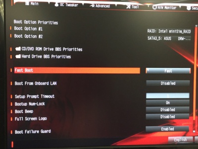
The BIOS change involves enabling Fast Boot. Fast Boot will disable your USB devices at boot-up thus preventing USB port conflicts and effectively preventing endless USB enumeration and rebooting.
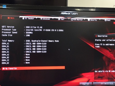
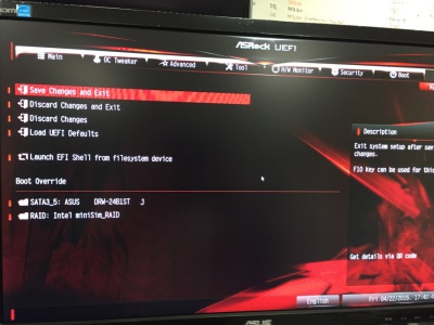
To enter BIOS setup, repeatedly press the Delete key while the computer is powering up. Ultimately you will see a screen that looks like the screen shot below. (This assumes your miniSim PC was built in 2015 or later.)
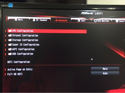
Navigate to the Advanced tab using the arrow keys on your keyboard and select it.
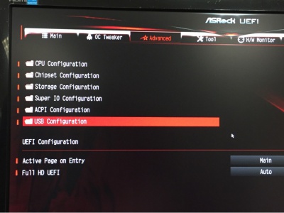
Scroll down and select USB Configuration.
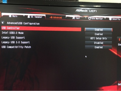
Make sure your BIOS settings match the settings on the right half of the screen as shown below:
Set Fast Boot to Fast.
Select Save Changes and Exit
NOTE: these settings will disable your USB devices during boot. This will eliminate the USB enumeration problem but will also prevent you from accessing BIOS settings again without a PS2 style keyboard. Feel free to contact NADS for additional information on this condition.
Bear in mind your BIOS screens may look different than the screenshots above but your objective remains the same, enable Fast Boot.
Please don’t hesitate to contact us if you wish help with these settings. Word of Caution: make these changes during normal business hours. If you get stuck in BIOS settings on a weekend or middle of the night, we may not be available to help you.
miniSim Software
Simulation data
Your data is the primary reason for simulation and is available from the miniSim in two ways:
- Default measures - these are pre-defined measures available for up to 20 events.
- Logstreams - the entire range of variables is available for as many events as required.
These two methods require setting up a scenario to create events that happen during simulation and are defined in a way to allow extracting them from the drive.
Default measures are available immediately after the drive in the form of a text document, located in the DAQ folder on miniSim.
Logstreams are flags embedded in the drive data and requires data reduction to make the information available after the drive.
More information on these methods is available here:
ISAT/Scenario
New to ISAT?
A quick start overview is available here.
The ISAT User Guide is available here.
A scenario/ISAT troubleshooting guide is available here.
Data Logging: miniSim Default Measures
There are a fixed number of measures available and a limit of 20 events.
More information including which measures are available and how to structure your scenario to support default measures is available here.
Q: How do we make an ADO or DDO go backward?
A: Only DDOs can back up. To accomplish this, start by placing a DDO where desired.
Next, create a path for the DDO; right-click on it and select Extend Path from the pop-up menu.
Then, lay out a path (path nodes are a sequence of yellow dots) to indicate the desired route of travel.
Finally, right-click on each node and select Rotate to set the direction that you wish the DDO to face. The direction at each node can be set independently.
In order to make it appear as though the car is moving backwards, the arrows should point against the direction of travel. To avoid erratic movement, you should add sufficient nodes to create a smooth path. This will result in smoother and more realistic movement of the DDO, especially if you are changing direction rapidly.
Q: How do I play a sound in my scenario?
Q: How do I add a trigger to my scenario?
Triggers can be added to a scenario in ISAT through the menu Insert >> Coordinators or, if the ISAT Elements panel is open, by left-click-drag any trigger off the panel and then releasing the left button where you want to place the trigger.
After a trigger has been placed in your scenario you can reposition it by clicking and dragging it to a new location.
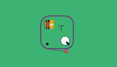
Note: Trigger consist of multiple elements. To reposition a trigger you will have to click-drag the trigger handle, which is a small red dot. Clicking the larger trigger pane will move the pane, not the handle. Moving the handle will move the trigger.
Some triggers also require a roadpad (roadpad, follow, Time To Arrival triggers). Right-click on the trigger and choose Place Road Pad.
Note: All triggers with road pads require a predicate to activate the trigger.
Q: What is a “Write to Cell” action?
Cells are reserved data containers that define various attributes and operating characteristics of the miniSim and are stored after each drive in a unique drive DAQ file.
A write to cell action allows you to send data to miniSim and simultaneously store this data in the DAQ file during simulation.
Most cells are managed by a subsystem (behaviors, dynamics, scenario control). For these cells, writing to a cell is possible but not practical because the managing subsystem will overwrite that cell within the next frame.
Examples (not a complete list!):
- Play a sound/audio file: Write to Cell SCC_Audio_Trigger
- Set event status or an event number for default miniSim data measures: Write to Cell SCC_Event_Status, SCC_Event_Number
- Saving data during a drive to the DAQ so it is available for analysis; i.e., timing of things, storing scenario variable data (variables are not persistent unless saved to a file or written to the DAQ): Write to Cell SCC_Custom1, or user defined
- Changing a simulator setting (Adaptive Cruise Control on/off, Automatic Lane Following): Write to Cell SCC_ALF_On, SCC_ACC_On
Note: Write to cell actions are expensive operations and there is currently a limit of 7 per frame. Exceeding this number will likely result in the excess cells not being written.
Note: Some cells are managed by the Cab Information/Hardware subsystem (CIS). Configuring miniSim to support operation by both scenario and CIS may require consulting with NADS to ensure correct operation.
Q: How can I tell if the driver has left the road?
One way to check if the driver has left the roadway is to use a lane deviation calculation: if the lane deviation is greater than <measured_total_lane_width> or less than -<measured_total_lane_width>, the driver is likely out of the lane. TOP
Q: How can I tell what surface the driver is driving over?
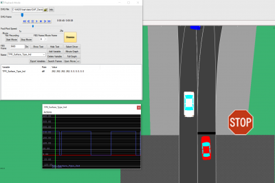
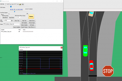
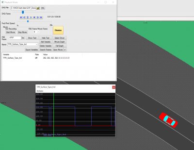
A. Use the cell TPR_Surface_Type_Ind to detect the surface material code (SMC) under the driver.
The first four elements of the TPR_Surface_Type_Ind correspond to 4 wheels of the ownship/external driver vehicle.
MiniSim does not report surface material codes within intersections that do not have an elevation map associated with them.
You can find a complete list of available surface material codes (SMC) - (not all of these are used in the tile library, but this is the current version for SMC codes) under the TMT\ProjectData\Tiles\CommonLRIData\SurfaceMaterialSpecifications.xlsx.
Note: Intersection elevation maps were introduced in TMT 1.8.5.


