NADS MiniSim Configuration Files
Location
There are six configuration files in text format for the NADS MiniSim. They are located under the folder %MININADSROOT%\data\config. The six files are:
- BrakePedalForceCurve.txt. It provides mapping from joystick brake pedal position to brake pedal force to be fed to the vehicle dynamics.
- Calibration.ecci_original.txt. It contains control input calibration values for the original ECCI steering wheel and pedal set.
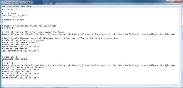
- CustomIconConfig.txt. It contains information of custom overlay icons such as the vigilance icons.
- customScaling.txt. It provides the scaling factor for correcting the aspect ratios of visual images rendered on displays set to resolutions that do not match their physical aspect ratios.
- JoystickButtonConfig.txt. It contains assignment of joystick buttons to various functionalities for multiple joystick types.
- AnalogButtonConfig.txt This file contains state configurations of multi-state buttons using analog input channels from daq boards. These buttons are found on OEM steering wheel button clusters. Measurement Computing USB, and US Digital USB4 boards are supported.
- SteeringInputCurve.ecci_original.txt. It provides mapping from physical steering angles of the original ECCI steering wheel to steering angles to be fed to the vehicle dynamics. This map is used to overcome the limited steering range of the ECCI wheel while not making it overly sensitive near the center position.
- titlerConfig.txt. It contains configuration information for the text overlay on the MiniSim video recording files when a video capture subsystem is running.
- EyeTrackerScreenConfig.txt. It contains layout information of the MiniSim display screens that is required for rendering driver gaze location when the eye tracker subsystem is running.
- DRT Settings.txt This file contains settings for communicating with the DRT (PDT) device
Syntax for the Configuration Files
All six configuration files are in text format and can be edited manually. However, it is recommended that the calibration file (Calibration.ecci_original.txt) be generated automatically using the calibration scenario. The other files have to be created manually.
All configuration files accept comment line that starts with a ‘#’. Empty lines are also allowed.
- BrakePedalforceCurve.txt
- Calibration.ecci_original.txt
- “ecci_original”, for the stock ECCI Trackstar 6000 wheel.
- “ecci”, for the hybrid ECCI wheel with shifter stalk. An eighth field is added at the end for shifter park position. The number of fields may be further expanded to thirteen or fifteen, depending on cab configuration. See comments in actual file for field designations.
- “happ”, for the hybrid HAPP board wheel with shifter stalk. An eighth field is added at the end for shifter park position. The number of fields may be further expanded to thirteen or fifteen, depending on cab configuration. See comments in actual file for field designations.
- “ecci_original”, for the original ECCI wheel.
- “daq”, for using combined MCCDAQ and US Digital USB4 daq boards for all inputs. This file is designed for truck MiniSim with thirteen fields. See comments in actual file for field designations.
- For the rest of the joystick types, they all use the generic “Calibration.txt” file with seven fields, the same as “Calibration.ecci_original.txt”.
- CustomIconConfig.txt
This file provides mapping from joystick brake pedal position to brake pedal force to be fed to the vehicle dynamics.
The first line contains a single value, the maximum pedal force in pounds. The ensuing lines provide mapping from relative pedal position to relative pedal force, both ranging from 0 to 1. Linear interpolation is used for interim values. The position value for a fully released pedal is 0, while that for a fully pressed pedal is 1. The relative pedal force, when multiplied with the maximum pedal force, provided the pedal force at a given pedal position
This file contains seven integers. They correspond to the digital readings from the joystick controls for the following conditions: center steering wheel position; extreme left steering wheel position; extreme right steering wheel position; fully released accelerator pedal position; fully pressed accelerator pedal position; fully released brake pedal position; fully pressed accelerator pedal position. This file should be generated automatically by running the calibration scenario.
For other types of joysticks, calibration files with appropriate names are used. The following strings can be used in place of “ecci_original” for appropriate joystick types:
This file contains custom icon information. This file will be loaded each time a scenario starts. For more control on the icon attributes such as colors, use the ISAT tool to define the icons within scenarios. Note: as of version 1.8.3.4, it is recommended that custom icons be defined as virtual objects in the scenario using the ISAT tool, which allows more flexibility in both setting up the appearance of the icons and in controlling the icons in the scenario.
For each icon, there are either five or six lines of configuration data.
The first line contains one or two strings. The first string specifies the name of the icon. The optional second string indicates the icon type. There are two types of icon available, OVERLAY and SCENE_OBJ. If type is not specified, the icon is treated as OVERLAY. OVERLAY type icons are rendered over the virtual environment, and will not interact with the contents of the virtual environment. SCENE_OBJ type icons are inserted into the virtual environment. It can be attached to a moving or static object in the scene, or it can be placed in the scene independently. Currently SCENE_OBJ can only be attached to the ownership vehicle. As a part of the virtual environment, SCENE_OBJ icons can be visually obscured by other objects in the scene.
The second line is a single integer, indicating the number of states the icon can have. In addition to those states, all icons have a default off state, which is state 0. The states of all icons can be controlled via the scenario
The third line is a list of integers, indicating the number of animation frames for each state. The size of the list matches the number of states. If a state contains only 1 frame, then it is a static state with no animation.
The fourth line is a list of animation sequence timing values. This line is present only if there are icon states that are animation sequences, i.e., there are numbers that are greater than 1 in line 3. The number of values in this line equals to the sum of all the numbers in line 3 that are greater than 1. The unit of the time values is seconds.
The fifth line is a list of texture file names or icon geometry description strings used for all the frames of all states. The total number of texture files and description strings should match the sum of the numbers on line 3. For animation sequences with an “off” frame, use “NULL” as the texture file name for that frame. Do not use “NULL” as the texture for static states. If a string is in the form of bordercolor_fillcolor_shape__, the frame corresponding to that string will be a colored geometric shape will border, otherwise, the frame will be a textured quad, with the string as the name of the texture file. For non-textured geometrical shapes, currently seven shapes are available: CIRCLE, TRIANGLE, RECTANGLE, HEXAGON, OCTAGON, STAR, and DIAMOND. The fill color and border color of the shape can be specified as one of the following ten: RED, GREEN, BLUE, YELLOW, ORANGE, WHITE, BLACK, GRAY, PINK, and PURPLE. For example, the string WHITE_RED_OCTAGON indicates a red octagon shape with white border.
The sixth line is the position, orientation and size of the icon. The content of the line is dependent on the type of the icon. For OVERLAY icons, there are seven fields in this line:
- Horizontal alignment for the icon. A string that can be “LEFT”, “RIGHT”, “CENTER”, or “NONE”
.
- Vertical alignment for the icon. A string that can be “TOP”, “BOTTOM”, “CENTER”, or “NONE”.
- Horizontal offset in number of pixels. For left or right alignment, it is the offset from the edge of the display. For center alignment, it is the offset to the right of the center (to the left if the value is negative). For “NONE”, it is the actual x coordinate in pixels.
- Vertical offset in number of pixels. For top or bottom alignment, it is the offset from the edge of the display. For center alignment, it is the offset above the center (below if the value is negative). For “NONE”, it is the actual y coordinate in pixels.
- Width of icon in number of pixels.
- Height of icon in number of pixels.
- Rotation angle of the icon in degrees. A positive angle rotates the icon counterclockwise, and a negative angle rotates the icon clockwise.
For SCENE_OBJ icons, the sixth line has nine fields: x, y, z, roll, pitch, yaw, width, height, and auto- rotation type. Since SCENE_OBJ is part of the virtual environment, its position, orientation and size values are like those of regular objects in the scene. The unit for position and size is feet, and the unit for rotation is degrees. The position and rotation values are relative to the origin of the parent object it is attached to, in this case the ownship vehicle. The coordinate system is as follows, as viewing from the driver: +x is to the right, +y is forward, +z is up, +roll is raising the left side, +pitch is tilting the top toward the driver, and +yaw is rotating to the left. Currently auto-rotation type can only be FIXED, indicating no auto rotation (auto rotation is to make the icon always face the driver).

