NADS MiniSim Configuration Files Continued
The sixth line is the position, orientation and size of the icon. The content of the line is dependent on the type of the icon. For OVERLAY icons, there are seven fields in this line:
- Horizontal alignment for the icon. A string that can be “LEFT”, “RIGHT”, “CENTER”, or “NONE”.
- Vertical alignment for the icon. A string that can be “TOP”, “BOTTOM”, “CENTER”, or “NONE”.
- Horizontal offset in number of pixels. For left or right alignment, it is the offset from the edge of the display. For center alignment, it is the offset to the right of the center (to the left if the value is negative). For “NONE”, it is the actual x coordinate in pixels.
- Vertical offset in number of pixels. For top or bottom alignment, it is the offset from the edge of the display. For center alignment, it is the offset above the center (below if the value is negative). For “NONE”, it is the actual y coordinate in pixels.
- Width of icon in number of pixels.
- Height of icon in number of pixels.
- Rotation angle of the icon in degrees. A positive angle rotates the icon counterclockwise, and a negative angle rotates the icon clockwise.
For SCENE_OBJ icons, the sixth line has nine fields: x, y, z, roll, pitch, yaw, width, height, and auto- rotation type. Since SCENE_OBJ is part of the virtual environment, its position, orientation and size values are like those of regular objects in the scene. The unit for position and size is feet, and the unit for rotation is degrees. The position and rotation values are relative to the origin of the parent object it is attached to, in this case the ownship vehicle. The coordinate system is as follows, as viewing from the driver: +x is to the right, +y is forward, +z is up, +roll is raising the left side, +pitch is tilting the top toward the driver, and +yaw is rotating to the left. Currently auto-rotation type can only be FIXED, indicating no auto rotation (auto rotation is to make the icon always face the driver).
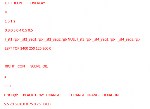
Below is a sample icon configuration file that contains 2 icons. The first icon has some animation sequences and so it uses six lines, while the second icon has no animation sequences and only uses five lines. The first icon is an OVERLAY type, and uses all textured quads for its frames. The second icon is a SCENE_OBJ type attached to the ownship vehicle, and uses textured quads as well as geometric shapes.
To control the custom icons specified in the icon configuration file through the scenario, use a variable that matches the name of the icon. Set that variable to a state number to switch that icon to that state. For example, using the above configuration file, one can set the scenario variable “LEFT_ICON” to 0 to turn off the left icon; set it to 1 to switch to the first state, which is a static icon; set it to 2 to switch to the second state, which is an animation with two “on” frames that last 0.3 second each and one “off” frame that lasts 0.4 second. The variable name is case sensitive.
customScaling.txt
This file provides the scaling factor for correcting the aspect ratios of visual images rendered on displays set to resolutions that do not match their physical aspect ratios. Each line contains three numbers, an integer for x resolution in pixels, an integer for y resolution in pixels, and a float for scaling factor. If a display setup matches the x and y resolutions in a line, the scaling factor in that line will be used. For example, a line
3072 768 1.333333
is used by a three-display triple-head adaptor setup with all three displays set to 1024x768, yielding a combined resolution of 3072x768. The aspect ratio by pixels is 4x3 per display. With the scaling factor applied, it becomes 16x9. This set up is used when the displays are 42” Panasonic HD plasma monitors, which have a physical aspect ratio of 16x9 but their native resolution is 1024x768. They also accept 1366x768 resolution, which is a 16x9 aspect ratio. However, the image quality under 1366x768 is poor compared to 1024x768. Therefore their native resolution is used instead, and the scaling factor is applied to maintain the correct aspect ratio in the visuals.
JoystickButtonConfig.txt
This file contains assignment of joystick buttons to various functionalities for multiple joystick types. Each line configures the button assignment for one type of joystick. The line contains joystick type string followed by 13 integers representing button numbers for 13 different functionalities, and optional button numbers for up to 20 auxiliary buttons, whose states are accessible in scenarios. The 13 functionalities are:
- Left turn signal switch
- Right turn signal switch
- Left wheel button (left vigilance button)
- Right wheel button (right vigilance button)
- Horn
- Cruise control switch
- High beam switch
- Left diamond button
- Right diamond button
- Top diamond button
- Bottom diamond button
- Up shift button
- Down shift button.
Any functionality assigned with a button number 0 disables that functionality. The button number of a joystick button can be looked up by running the joysticktest program. With the program running, press the button in question, and look for the value under “dwBtns”. For button number n, its dwBtns value should be 2^(n-1). Make sure only one button is pressed when checking (the value under “dwBNum” should be 1).
Valid joystick types are:
- ECCI, for the hybrid ECCI wheel with shifter stalk.
- MSJOY, for generic MicroSoft wheel.
- LOGITECH, for Logitech Gamepad.
- LOGITECH_G25, for Logitech G25 wheel.
- HAPP_UGCI, for the hybrid HAPP board wheel with shifter stalk.
- LOGITECH_WINGMAN_FORMULA_GP, for Logitech Wingman Formula GP wheel.
- LOGITECH_G27, for Logitech G27 wheel.
- ECCI_ORIGINAL, for the original ECCI wheel.
- FANATEC_GT3RS, for the Fanatec Porsche 911 GT3 RS wheel.
- DAQ_BOARDS, for using combined MCCDAQ and US Digital USB4 daq boards for all inputs.
The states of the optional auxiliary buttons can be accessed by reading the MiniSim cell variable CIS_Auxiliary_Buttons, which is an array of 20 floats. With the introduction of the two types of daq boards, the digital and analog input channels from those two boards can be used as button states as well. The use of daq boards is independent of joystick type. In other words, as long as one or both daq boards are present, their input channels can be used as buttons, even if the joystick type is not “DAQ_BOARDS”.
- For USB4 digital inputs 0 to 7, use button numbers 1000 to 1007.
- For MCCDAQ digital port A inputs 0 to 7, use button numbers 2000 to 2007.
- For MCCDAQ digital port B inputs 0 to 7, use button numbers 2100 to 2107.
- For USB analog inputs 0 to 3, use button numbers 1100 to 1103. Corresponding entry in configuration file “AnalogButtonConfig.txt” is required.
- For MCCDAQ analog inputs 0 to 7, use button numbers 2200 to 2207. Corresponding entry in configuration file “AnalogButtonConfig.txt” is required.
Buttons from digital inputs can have states 0 (unpressed) or 1 (pressed). Buttons from analog inputs can have multiple states, mapped from input voltage. To configure multi-state buttons from analog inputs, use the configuration file “AnalogButtonConfig.txt” (see section below).
If no auxiliary buttons are defined in the button configuration file, the left and right wheel buttons will be mapped to auxiliary buttons 1 and 2, respectively. Please refer to the ISAT user manual on how to access MiniSim cell variables in a scenario and its potential uses.

