Settings button
Contents
Settings Button
There are several system behavior settings available. Click on the Settings button.
Screensaver
If the Enable Screen Save option is checked, when the miniSim stays in the stopped mode for a prolonged period of time, the screen saver mode will start automatically, with the visuals showing a chase view and replaying a pre-recorded drive. As soon as the “Start Drive” button in the GUI is clicked, the screen saver mode will stop. The Windows desktop screen saver on the visuals computer is automatically disabled when the miniSim visuals is running.
If a screensaver file does not exist for your visual database, or you just created a new database, use the following procedure to create a screensaver file:
Data Collection Mode and the DAQ Button
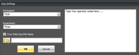
The miniSim data acquisition system (DAQ) runs every time a scenario is run. However, when the miniSim is placed in Data Collection Mode, the operator must select the Experiment Name and Test Subject ID from a list you create. The Experiment and Test Subject ID selected then restricts the allowable scenarios that can be run according to a matrix defined by the user – ensuring that the data collection conforms to your experimental design. In addition, you may enter notes or comments about a particular test subject or drive and these comments are saved for future reference, Figure 23. You may also manually enter The Experiment and Test Subject ID at runtime.
Every time a scenario is run on the miniSim a data collection (*.daq) file is created. DAQ files are located in the C:\DAQ folder. Checking the Data Collection Mode box simply changes how the data collection interface works.
With the box un-checked:
- When the Data Collection Mode is un-checked, all DAQ files are saved in the C:\DAQ\Texpr\Tsub folder
- TExpr stand for ‘Test Experiment’, and Tsub stands for ‘Test Subject’
With the box checked:
- When the Data Collection Mode is checked, the DAQ button is used to select the experiment
- The two pull-down menus for the Experiment and Participant are used to select correct participant ID.
- The participant ID chosen restricts the available scenarios to those specified in your experimental design
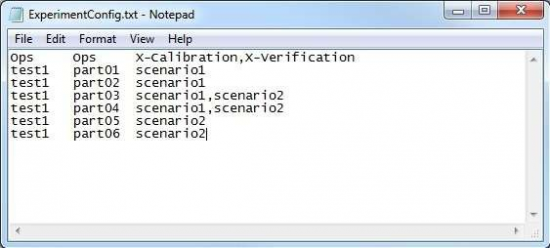
- You create the experimental design using the ExperimentConfig.txt file located in the C:\NadsMiniSim_v1.8.x\Data\Rcm_data folder. A sample file is shown below. The first column is the experiment name, the second column is the test subject name, and the third column is a comma-separated list of the allowable scenarios for that participant. Note the use of the ‘Ops’ Experiment to allow use of the calibration and verification scenarios only to the operator.
- When in DAQ mode, the operator may enter notes about the participant or drive, and these are recorded in a text file located in the C:\DAQ\Texpr\Tsub folder. The construction of the filename is as follows:
- Scenarioname_timedatestamp_notes.txt
The miniSim can also be launched from a DOS prompt. This command line options to do this include the option to specify exactly where each DAQ file is to be located. This covered in a later section.
Show Report After Drive
When this box is checked, and the scenario is properly authored, the miniSim will display measures in a pop-up window immediately after the completion of a drive. The same measures are recorded in a text file located in the C:\DAQ\Texpr\Tsub folder. The construction of the filename is as follows: Scenarioname_timedatestamp_report.txt
If this box is not checked, the miniSim will still calculate measures, and record them in the text file, but not display them in the pop-up window.
The current list of measures that are calculated are as follows:
The scenario must be set up so that the measures will be calculated. There are two variables that must be initialized in the scenario and incremented to define the ‘events’ in the following way. Note All must be set to type short :
- At the start of a drive, use a road-pad trigger to set SCC_EventStatus =0 and SCC_EventNumber = 0.
- At the start of the first event, set SCC_EventStatus = 1 and SCC_EventNumber = 1
- At the end of the first event, set SCC_EventStatus = 0.
- At the start of the second event, set SCC_EventStatus = 1 and SCC_EventNumber = 2.
- At the end of the second event, set SCC_EventStatus = 0.
- Continue in the pattern, and at the end of the final event, set set SCC_EventStatus = 0.
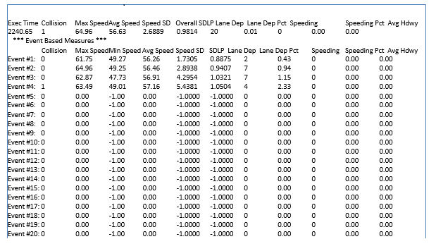
The report format is as follows. Note that the results in the first line are for the total drive starting with the first event and ending with the last event. Only four events were defined for the example below.


