TMT Troubleshooting Guide (all versions)
This guide has been created for when things go wrong during the process of using the TMT to assemble and create database worlds for use on the NADS miniSim™.
Please note: any steps that call for making changes to files should proceed carefully to prevent problems. In general, backing up a file is preferred to removal.
Contents
ADOs Can't Travel On Sections of the Road Network
There are two common causes for this issue which must be corrected using TMT in order for traffic to operate as intended on a road network.
- Road map contains a discontinuity or break.
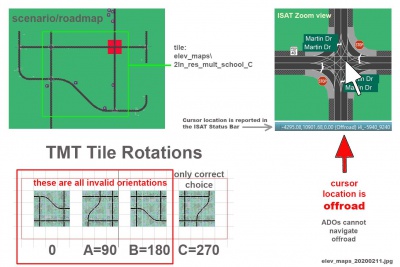
- The other cause for ADO failure is the use of tiles containing elevation maps. These tiles follow an orientation code that must be strictly followed due to the nature of the meta-data that defines surfaces within the intersection area. In cases where the proper orientation is followed, ADOs can navigate without any problem. However, use of an elevation map tile with the incorrect orientation will introduce an off-road area that ADOs cannot travel on.
These places can be identified by ADOs attempting to fly (taking off the surface of the road like an airplane). They disappear soon after. This problem will also be evident in ISAT because ADOs will disappear during rehearsal when they encounter this situation.
You can confirm the situation by reviewing the TMT project and reviewing the tile category for the intersection location in question. Elevation maps at present are limited to intersection tiles only.
You can also mouse over the suspect area in ISAT, and watch the status bar as the cursor moves. Note how ISAT reports the cursor is over a road when the cursor is over a road, or within an intersection when the cursor is over an intersection. If ISAT reports "off road" when the cursor is within an intersection, the tile orientation does not match its elevation map orientation.
Note that not all elevation map tiles are present for all orientations.
Output Visuals failure
In the event TMT cannot generate visuals, address the following:
- Is the output disk full?
- Is the output location in a Windows reserved area (Program Files) or other permission restricted folder?
If neither of the above options are true yet TMT cannot generate visuals, please contact the miniSim support team.
Output LRI failure
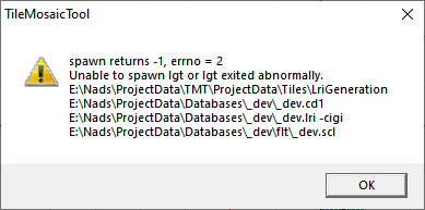
If TMT cannot generate the LRI file the most common error will present an error dialog:
The most common cause of this error is a TMT configuration error. The TMT is not able to locate the program that is executed by the Generate Output >> LRI function.
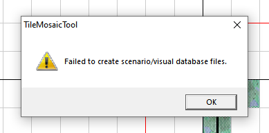
This is an associated message displayed after the spawn dialog.
To address TMT configuration issues please contact the miniSim support team.
LRI failure workaround
To generate an LRI file from the command line/DOS window, you can run the lg (el g) script from the TMT project folder. This is a folder that contains all the TMT project files (.mos, .cd1, .cd2, flt folder).
Unable to write LRI file
- Is the output disk full?
- Is the output location in a Windows reserved area (Program Files) or other permission restricted folder?
If neither of the above options are true yet TMT cannot generate the LRI file, please contact the miniSim support team.
Failures During File Processing
There are a number of steps required to produce a drivable scenario on the NADS miniSim™ simulator. These steps can be classified as file processing in that they require you to perform some operations in order.
Buildscl command fails
In the case where the buildscl command fails:
Unknown command
- 'buildscl' is not recognized as an internal or external command,
operable program or batch file.
This error indicates a configuration error and it happens if the buildscl.exe file is not at an expected location within the TMT installation folder.
To resolve this issue it will be necessary to review the folder structure of the TMT install to see if it is out of compliance with the standard installation.
It may be necessary to contact the miniSim support team to address.
- The command name was mis-typed
Review the command and re-run it if there is a spelling error.
- Error: must supply an input file name
The buildscl command requires a file name to process. The only valid input is an OpenFLight™.flt file.
Re-input the command and supply a valid .flt file. The file should be visible/present if you run a dir command. In almost all cases this will mean running the buildscl command from within a TMT project flt folder, as in the following example:
e:\Nads\ProjectData\Databases\_dev\flt>dir _dev.flt
Volume in drive E is User
Volume Serial Number is 0878-963A
Directory of e:\Nads\ProjectData\Databases\_dev\flt
08/10/2021 10:11 AM 1,880 _dev.flt
              1 File(s)          1,880 bytes
              0 Dir(s)  1,890,924,244,992 bytes free
Error running buildbatchlist script
If this command is not recognized, it indicates a TMT configuration error.
Error executing do or buildbatchlist scripts
During processing messages from the converter are echoed to the command window. If any of these messages indicate a missing texture or file cannot be found, it is due to a file missing from the expected location.
NADSTMT_x.x\ProjectData\TexRGB
Note: the TMT root folder may be called something other than NADSTMT or NADS_TMT or something similar.
Failure During BLI Generation
There are two ways to generate a BLI file:
1. TMT
If the TMT is not able to launch the BLI tool it is likely due to a TMT configuration error. Contact the miniSim support team.
A workaround for the TMT BLI failure is to use the mlri script.
2. mlri script mlri <your_db_world.lri><Enter>
If the mlri command is not recognized it is possibly due to a TMT configuration issue.
Review the folder locations within Nads_TMT\ProjectData\utils\nadsconfig_system.bat and ensure the variables are set to valid folder locations on your miniSim.
If the command fails to run it could be due to an error in the command input string.
The mlri script does not require the use of a file extension - if present the script will attempt to run on file.lri.lri. This is incorrect. Re-run the command without the file extension.
BLI Errors
Some warnings may show up during the BLI generation process. The important problems are errors and they can prevent the creation of a valid BLI.
Gap tolerance warning
The BLI tool will not create a BLI if it encounters a gap larger than the tolerance provided in the mlri script which defaults to 1.0 units (1 foot).
You can override the default tolerance by supplying a tolerance with the mlri command:
mlri <input.lri> <new_tolerance_value> <Enter>
Points out of order
This error indicates the BLI tool has encountered a catastrophic error and cannot process the LRI input. It will be necessary to correct the cause of this problem before the BLI file can be created.
There are two common causes of this error. One can be corrected by you, and the other may not be.
- Orphan tile: any single tile segregated by the overall road network.
- A tag defining a road within a tile is not located at the road origin, causing the road path to double back on itself during BLI creation.
For Orphan tiles, identify the orphan and remove it from the roadmap by deleting it from the TMT workspace. If the tile is a necessary element of your project, find some way to connect it to your road network.
- identify a coordinate point (X, Y) in the error message.
- Open the TMT project for the BLI and zoom out in the workspace so you can see the entire roadmap. You should be able to see all the tiles being used. If you cannot zoom out far enough, process each visible section until you can identify the tile at or near the coordinate.
- Identify the tile under/near the coordinate.
- If the tile is not an orphan, then navigate to the tile folder identified:
NADS_TMT\ProjectData\Tiles\<tile_category>\<tile>
- Examine the start coordinate for all .path files. Compare that coordinate with the coordinate associated with that road definition in the tile.pet file. They should match.
In cases where the points do not match, edit the .pet file so the tag location coordinate matches the actual road data start point.
In the event the .pet and .path coordinates match you may find it necessary to contact the NADS minisim support team.
Force Tile Placement
The TMT relies on data within each tile to determine compatibility when a tile is positioned next to another tile.
In some cases the tiles do not connect, and a red edge will display wen you attempt to place incompatible tiles.
You can override TMT by doing a 'forced placement'. However, such an operation does not guarantee the resulting road network will be suitable for use by simulated traffic.
These attributes determine if a tile is compatible with another tile:
- road number of lanes
- road or lane width
- edge labels along outer edge
If the road lanes or widths do not match, the TMT will allow forcing the tiles together but the result will be a road network that simulated traffic cannot navigate during simulation.
This isn't a problem for cases where the only traffic is the external driver. However, simulated traffic will not negotiate the road network across forced edges. Instead, the vehicles will disappear when they reach the end of the logical road.
A forced placement has no obvious effect if traffic is not intended to travel across the forced edge. For example, to place a filler tile next to a road tile will require forced placement, but traffic will not be expected to traverse that edge. In this case it is alright to proceed.
Objects Not Controllable
Objects that are visible in ISAT are generally controllable by choosing an option on the object, whether it is a traffic sign or a terrain feature.
However, objects may not be controllable in ISAT due to the TMT project configuration even if you can change them in ISAT. In order for an object to be controllable, the TMT project must be properly configured to support it. In general, this applies to intersection and interchange tiles because they contain many sign objects.
A detailed description of the problem is presented in the ISAT User Guide.
There may be additional features present in the tile that could be controlled such as road surface, pavement markings, billboards and other features.
One possible issue can be identified by reviewing the world.lri file as ASCII text and identifying the object/s you wish to control. All controllable objects are located near the end of the LRI file in the OBJECTS section. Each object should have a unique, non -1 ID assigned to it. Objects that have an ID of -1 are not controllable in the BLI.
In some cases the tile may be missing from TMT\Tiles\CommonLRIData\tileSizes.txt. In that case add the tile to the bottom of the file following the conventions for the other entries listed: tile_name.flt x_size y_size
Note: size is in Tile Units, or 660f increments. This information can be found at the top of the tile.pet file, located in the tile folder under each category.
Object Controllability Pipeline
This section contains technical detail regarding object controllability.
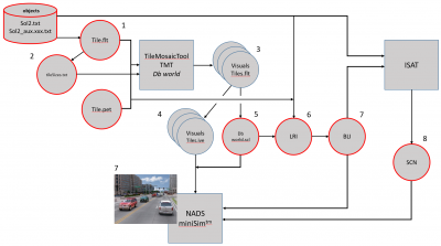
The following diagram illustrates the controllability pipeline and how the various components are related to each other to arrive at a controllable object on the miniSim.
Each downstream element is dependent on upstream elements. Any failure in the pipeline will result in objects that are not controllable; i.e., those objects will display only their default settings during simulation irrespective of the scenario settings authored for it.
Controllable objects are specified in the sol2.txt or sol2_aux.xxx.txt, and are referenced within a tile model using appropriate syntax. This information is extracted from the tile model and stored within the tile.pet file, which contains all meta-data for the tile:
- road definitions
- intersection definitions
- objects that are not controllable in scenario (street lights, parked cars, terrain, features)
- objects that are intended to be controllable in scenario (signs, features)
Object controllability is specified in the Scenario Object List file, sol2.txt or sol2_aux.xxx.txt by the use of multiple Option keywords. The following section is the sol2 definition for a Stop sign. Note the Options are defined as Yield, Stop, Stop All Way and Off.
TrafSign Stop
 Width
  0.9
 &end&
 Height
  3.0
 &end&
 Length
  0.1
 &end&
 VisModelCigiId
  803
 &end&
 ObjID
  803
 &end&
 CanBeAdo
  0
 &end&
 CanBeDdo
  0
 &end&
 CanBeStatic
  1
 &end&
 IsatModelBitmap
  "stop.bmp"
 &end&
 IsatModelHighLod
  ""
 &end&
 IsatModelLowLod
  ""
 &end&
 Option
  0 "Yield" "yield.png" "" ""
 &end&
 Option
  1 "All-way Stop" "stopAll.png" "" ""
 &end&
 Option
  2 "Stop" "stop.png" "" ""
 &end&
 Option
  3 "Off" "off.png" "" ""
 &end&
 DefaultSoundID
  0
 &end&
 CollisionSoundID
  0
 &end&
&end&
Object Controllability: Stop Sign in ISAT
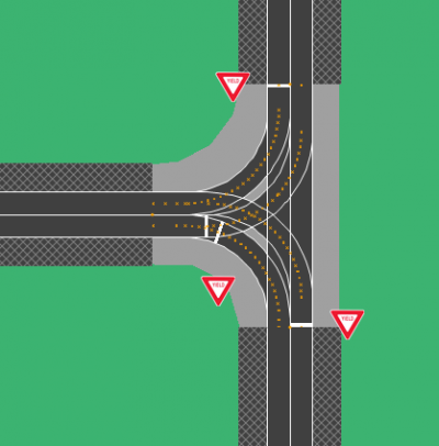
The following image shows a 3-way intersection with the signs in their default state, which is the first option defined in the SOL2.txt file.
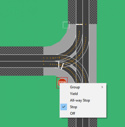
Options are shown by right-clicking on the object as shown below:
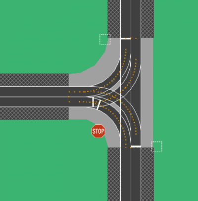
Selecting the desired option is accomplished by choosing an option presented in the context menu to produce the desired results, such as disabling signs for a main road while setting the secondary road to a stop sign as shown below:
NOTE: Just because an object is authorable in ISAT does NOT guarantee the object is really controllable, or will be represented during simulation as authored in the scenario.
In order to test the scenario it is necessary to drive the scenario on miniSim™.
Note: ISAT has a known bug that randomly resets scenario objects to their default setting. A workaround exists by using an external reference scenario file to set signs and features, then referencing that file from your main scenario file. This method prevents ISAT from changing object settings.
