Working with Components
ISAT User's Guide Table of Contents
Contents
Working with Components
Components are a mechanism by which scenario elements can be grouped together for re-use.
Emailing Scenarios
To e-mail the current scenario, select the File->Email Scenario menu option. The default e-mail program will appear with an attachment that contains the current scenario.
Printing the Map
To print the map, select the File->Print menu option. In addition, all standard Windows print dialog boxes work as expected, including Print Preview and Print Setup. Note that only the area of the map displayed on the tool’s work area is printed. As a result, be sure to adjust the view port as necessary before invoking the Print menu. If in doubt, use Print Preview to ensure that what will be printed is what is intended.
Adding Scenario Comments
To associate a textual comment with a scenario, select the Edit->Scenario Comment menu option. It is recommended that long descriptive descriptions be added for each scenario to make it easier to remember the goals of a scenario that was built by others. Keep in mind that the scenario comment appears in the preview window when opening an existing scenario file (see Section 3.5 for more details).
Comment Objects
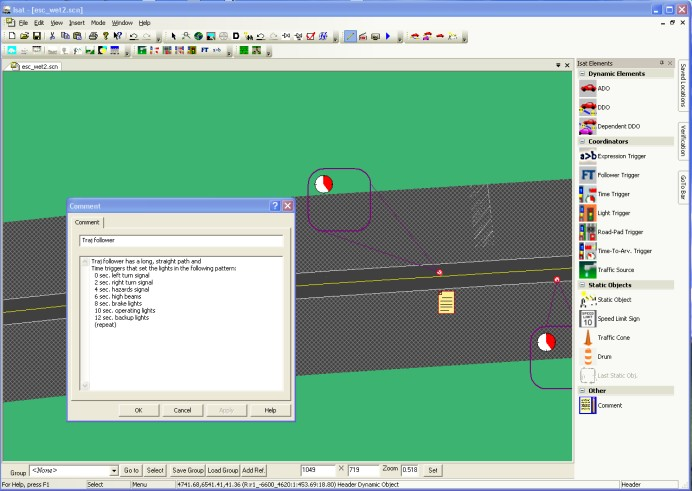
When authoring a scenario it often becomes necessary to create complex events made up of multiple triggers and actions. Because of this, it may not be easy to understand the purpose of a specific group of triggers and other scenario elements when looking at them. It may then be necessary to insert a comment object to describe the goal of a group of scenario elements. This is particularly true if the scenario is likely to be reused in the future. The comment object is denoted by a piece of paper, and is inserted just like any other scenario object. If you double click on the comment object, it brings up a text box. The contents of the text box are stored in the scenario. Scenario objects are only used by ISAT in editing mode, and will not affect anything else.
Defining Common Scenario Element Parameters
For consistency and ease of use, most scenario elements use a similar definition method with a tabbed dialog box where the user can specify the various parameters. These dialog boxes are scenario element-specific; however, they all contain a set of common parameters that have similar functionality, independent of the scenario element. These parameters are defined below.
Name
The name of a scenario element is used to identify that element in the scenario. The ISAT does not force scenario elements to be unique, so it is up to the user to ensure that when a scenario element will be referenced somehow in the simulation, then that name should be unique.
Creation Radius
The creation radius is a threshold in the distance between the scenario element and the position of the simulator driver. At runtime, the element will not be created until the actual distance between the position of the simulator driver and the scenario element is less than or equal to that threshold. For example, consider a scenario element placed at position (0, 0), a creation radius of 300, and an initial position for the simulator driver at location (500, 0). When the scenario begins, the actual distance will be 500, which is larger than 300. Therefore, the scenario element will not be created. What this means in the simulator is that there will be no visible entity at location (0, 0). Furthermore, the computational load on the scenario caused by this element is minimal. Now consider the situation where the simulator driver is driving toward the location (0, 0). The range between the scenario element and the driver is continuously monitored, and when that range gets below 300, the scenario element will be created. In the above example, this will take place when the driver reaches the location (300, 0). The actual effect of the creation varies depending on the nature of the scenario element. For example, if the scenario element has a visual representation (it could be, for example, a stopped vehicle), then this is the time when that vehicle will appear in the simulator’s virtual environment.
The creation radius only affects when a scenario element is created; it does not affect the deletion of a scenario element. In other words, if after creation the range between the driver and a scenario element exceeds the creation radius, the scenario element will not be deleted automatically.
Note that the range between the scenario element and the driver is measured along a straight line, not along the road network. It is the user’s responsibility to ensure that the creation radius is large enough or that the initial position of the scenario element is occluded so that the simulator driver does not observe the creation of the scenario element.
The rationale for having a creation radius is twofold. First, it helps manage the computational load of the system by not creating scenario elements until near the time they will be used. Second, it can be used as a simple authoring mechanism where the rough timing of events is controlled by the motion of the simulator driver.
In the ISAT, a creation radius is shown as a red circle around the element. The default value for the creation radius is 0, which indicates that no such constraint is in effect and the scenario element will be created at the beginning of the scenario.
Activation Delay
The activation delay is the number of seconds between the time a scenario element is created and the time its behavior is engaged. The default value for this parameter is 0, indicating that an element will begin acting as its behavior dictates immediately upon its creation. Note that, upon creation, the visual representation of that element, if any, will appear in the simulator’s virtual environment, even if an activation delay is in effect.
The activation delay is often useful in conjunction with a creation radius. Using a larger than needed creation radius can help minimize the chance that the simulator driver will observe an object popping out of nowhere, and the activation delay can ensure that the object does not begin its activity until the driver is closer. For example, consider a DDO vehicle that is programmed to begin traveling at 50 mph, has a creation radius of 500, and has an activation delay of 3. Once the driver gets within 500 feet of the DDO, the DDO will be created and the vehicle will appear in the virtual environment. However, another 3 seconds have to go by before the DDO will begin moving.
Lifetime
The lifetime is the maximum number of seconds that a scenario element will exist. The time of existence begins when the scenario element is created. Once the lifetime is reached, the element is automatically deleted. Like the other parameters, the lifetime is useful in controlling the computational load of a scenario. Having a finite lifetime ensures that a scenario element does not consume computational resources long after it has performed its task within the scenario.
The default value for the lifetime is 0, which indicates that the maximum lifetime will extend until the end of the scenario (unless, of course, the element is explicitly deleted through other means).
It is the user’s responsibility to ensure that the lifetime, if specified, is large enough to ensure the scenario element is not close enough for the driver to observe its disappearance.
SOL Model
Most scenario elements have a visual representation associated with them. It is important to realize that, in general, the visual representation is decoupled from the behavior of a particular object. Behavior refers to whether the object is a DDO, ADO or static. Visual representation refers to what the object looks like. The visual representation is selected among existing objects contained in the Scenario Object Library (SOL), a library containing numerous objects, their visual representations, and additional properties such as their audio signatures or terrain effects. Objects in the SOL are grouped in categories. Objects in the same category have similar properties and are conceptually similar. For example, all objects of category Truck have a parameter “weight”; however, each object can have its own value for that parameter. At this point, the actual parameters and their values are not visible to the user but are maintained by the SOL internally. See Appendix A for a detailed description of the SOL categories and objects.
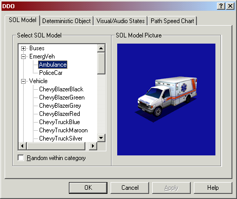
The SOL model to be used for all behaviors is selected through a consistent tab in the scenario element’s dialog box. Figure 3-37 illustrates this dialog box tab, as shown within the DDO definition dialog box. There are two components to the dialog box. On the left, a list box contains the SOL categories in a two-level hierarchical tree display. The top level is the category name and the lower level is a listing of the available object types in that category. For example, as shown in Figure 3-37, the category EmergVeh contains two object types named Ambulance and PoliceCar. Clicking on an object highlights the entry and at the same time displays a visual representation of the object on the right side of the dialog box. The selected entry is the one that will be used for the behavior of the object being authored by the dialog box.
Keep in mind that the actual SOL categories appearing on the left side of the dialog box will vary depending on the actual behavior of the enclosing dialog box. Specific SOL categories will be omitted when it makes no sense to associate an object of that category with a behavior. For example, there is an SOL category named "Signs" whose objects are various regulatory signs. This category does not appear in the SOL selection list shown in Figure 3-37, which is used for defining DDOs. Associating a sign object with a DDO would result in a sign that moves about the virtual environment.-
Occasionally, there will be objects that have no convenient visual representation. For example, there is a category named POI which stands for Points of Interest. It includes objects such as audio generators that cause sound effects in the virtual environment but have no visual representation. The picture displayed for such objects is a red X.
The SOL has been designed so it can be extended with additional objects or even additional categories. Adding new objects involves creating entries for the various NADS-correlated databases, such as the visual and audio databases, and rebuilding the NADS software. Although this process is not complicated, it requires access to all the NADS software and intimate knowledge of the software’s structure. Therefore, it is not possible at this time for ISAT users to extend the SOL.
Buttons and Dials
All scenario elements that can be authored by ISAT exhibit some form of behavior when activated in the virtual environment. The complexity of this behavior varies. By far the simplest behavior is associated with the Static Objects. Specifically, they appear and stay put in a fixed location in the database. The ADOs exhibit the most complex behavior through their driver model. To allow orchestration of events within scenarios, the default behavior of the various scenario elements can be changed at runtime. The mechanism used to implement behavior changes is access to buttons and dials. Buttons and dials are conceptual models for inputs associated with each behavior type and operate much like physical push buttons and analog dials everyone is familiar with. Specifically, a button is an input mechanism that when pressed, provides a one-time binary signal to the behavior. Similarly, a dial is an input mechanism that, when set, provides a perpetual analog signal to the behavior. The actual effect of the delivered signal depends on the behavior itself, the state of the scenario element when the signal is received, and the button or dials itself.
For example, consider an imaginary dial associated with the DDO behavior. The name of the dial is Speed. Setting the dial has the effect of changing the speed of the DDO for the remainder of its lifetime. As another example, consider an imaginary button associated with the ADO behavior. The name of the button is TurnLeft. When pressed, this button signals the ADO that it should take the next turn to the left rather than whichever direction it was going to take.
Note that buttons and dials provide a "suggestive" means of control, not an explicit one. This implies that a given behavior may decide to ignore a signal delivered though a button or dial if it cannot gracefully fulfill the request. For example, if the TurnLeft button press came at a time when it was not possible to make a left turn, that request would not be fulfilled. At the same time, if a particular behavior defines that a given button or dial has a direct effect, then the responsibility of reasonable behavior is passed to the user. Again, consider another example of a dial associated with an ADO named ForceVelocity. If this dial is set, the ADO will travel at that velocity, no matter what. However, setting the speed to a fixed value could cause collisions or make the car run off the road.
For each type of behavior that can be authored by the ISAT, this document will provide a listing of all buttons and dials and a description of how they will affect the behavior at runtime. At runtime, the actual pressing of buttons and setting of dials is done though coordinators such as the trigger or, to some limited extent, interactively by the user though the ISAT. The rehearsal mode of the ISAT can then be used to execute the scenario and verify that the runtime behavior is what was expected.
Group Bar
The group bar has many useful features, mostly dealing with groups. A “group” is a group of scenario elements. The go to button cycles through the group members whereas the select button selects all the members of the group.
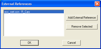
Groups can be saved to a file, or loaded to a file. To save a group select the group name in the group combo box, and hit the “Save Group” button. This saves the group to a .grp file. This file can be loaded into other scenarios. To load a group from a file hit the “Load Group” button. The Add Ref. button will bring up the external references window. From here, you can add and remove external references. The left hand side of the colon in Figure 3-39 is the scenario name the reference is from, and right hand side is the group name.
The difference between adding a reference, and loading a group from a file, is that the when adding a reference, the group is stored in the original scenario, and cannot be changed in the current scenario. The group members can be changed by making the changes in the original scenario. Loading a group from a file, adds the group to the .SCN file. The elements from the group are just like any other element, and can be changed in the current scenario. Changes to the original group (*.grp) file will not have an effect on the scenario elements that have already been loaded.
Scenario elements can be added to a group by right clicking of them and selecting the group menu, from the context menu. A check will appear next to the group name the element belongs to. The “New Group….” option will allow you create a new group, and add the currently selected element or elements to the new group. Note: you cannot change group membership through use of the group drop-down on the group bar; this is new as of version 1.5.0.
The right most three edit-boxes in Figure 3-38 can be used to set the current screen resolution and zoom level. This is useful for recording movies as it allows the setting of the exact resolution and zoom level. Hit the set button to set the resolution and zoom level to the values specified in the edit-boxes. To change the zoom and not the resolution, leave the two resolution boxes empty (the two boxes on either side of the X) and hit set. Conversely to change the resolution and not the zoom leave the Zoom box empty and hi the set button.
Preferences
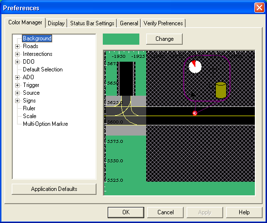
ISAT preferences can be set by opening the preferences windows through Edit- >Preferences menu. The preferences window has 5 tabs controlling Colors, Displays, Status Bar, General Settings, and Verify preferences.
The Color manger tab, as it the name suggests is where you can set the display colors for the map. You can set the road color, color of the background and other settings.
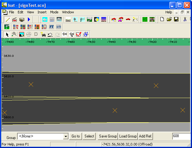
The display tab allows you to set some general display options. Currently the only two options in this tab are, Show Exact Roads and Show Control Points. The control points will show up as small X’s on the screen as seen in Figure 3-41. Show exact roads forces ISAT to use an exact representation of the roads instead of a slightly simplified model that it usually uses. This feature as of version 1.1.36 does not work. This may be fixed in future versions.
The status bar settings tab allows you to set the information that is displayed on the bottom of the screen. Information such as x,y coordinates and Speed Limit can be set here.
The General Preferences tab includes two options, Automatically Check ISAT for Updates, and Auto-Save. The Automatically Check for ISAT Updates option when enabled ISAT checks on the local network if a new version of ISAT is available when ISAT is first opened. If a new version is available then ISAT will prompt the user if they want to update to the new version. The Auto-Save options saves a back up copy of the current scenario being edited every 5 minutes. If no changes to the document have been made or the document is not in edit mode then no back up files will be saved. ISAT saves the files as Your-Scenario- Name.SCN.BAK. In order to restore a back up, rename it to your-scenario.scn and open it up in ISAT as usual.
The Verify Preferences tab sets the Verification tool preferences. The Verify at Save option is set, ISAT launches the verification tool at save, if any errors are found the verification window is then displayed.
