Difference between revisions of "Advanced Topic 13 Continued"
Anna Dizack (Talk | contribs) |
|||
| (2 intermediate revisions by one other user not shown) | |||
| Line 1: | Line 1: | ||
| − | [[Advanced_Topic_13| PREVIOUS]] [[Advanced_Topic_13_Continued II| | + | [[Table of contents|Table of Contents]] |
| + | |||
| + | [[Advanced_Topic_13|◄ PREVIOUS]] [[Advanced_Topic_13_Continued II| NEXT►]] | ||
==Eye Tracking== | ==Eye Tracking== | ||
| − | The eye tracker sub-system on the | + | The eye tracker sub-system on the miniSim, is an application that listens for data from Face Lab version 5 system, and adds to it to the miniSim’s shared memory, where it is then recorded by the DAQ subsystem. The miniSim DAQ logs the eye tracking frame number. |
| − | To enable the | + | To enable the miniSim’s eye tracking sub-system, open the '''C:\NadsMiniSim_X.X\Data''' folder and open either the '''NADSMiniSim.nocab.daq.sf''' or '''NADSMiniSim.nocab.daq.acc.sf''' files depending on if ACC functionality is required (See Advanced Topic 11 – Scheduler Files) |
To enable the eye tracking subsystem, comment out using the # symbol the appropriate lines: | To enable the eye tracking subsystem, comment out using the # symbol the appropriate lines: | ||
| Line 12: | Line 14: | ||
To disable the eye tracker, replace the # symbols. | To disable the eye tracker, replace the # symbols. | ||
| − | Next, setup the Face Lab eye tracking system itself. The eye tracker needs to connect to the | + | Next, setup the Face Lab eye tracking system itself. The eye tracker needs to connect to the miniSim over Ethernet. Connect the eye tracker PC to the MiniSim Pc through the use of an Ethernet switch (note the above diagram). Once the computer hosting Face Lab has been connected to the miniSim, now you need to instruct face Lab to forward data to the miniSim. This is done on the “Controls” dialog in face Lab, select the “Logging” panel. Select “Log Real-time”, under Network Address, type in the IP address of the miniSim. The port number should be set to 2020. |
When doing ‘precision’ eye tracking in Face LAB 5.0, you must also set the eye tracker to log to disk. | When doing ‘precision’ eye tracking in Face LAB 5.0, you must also set the eye tracker to log to disk. | ||
| Line 18: | Line 20: | ||
[[File:disk.png|550px|thumb|center]] | [[File:disk.png|550px|thumb|center]] | ||
| − | Once the communication between face Lab and the | + | Once the communication between face Lab and the miniSim have been set up, you will need to start logging. Once a model has been setup, you hit the “Start Logging” button (as seen in the picture bellow) on the model dialog. This will start sending data to the MiniSim, and you should get Eye tracking data recorded in the DAQ file. |
[[File:eye.png|550px|thumb|center]] | [[File:eye.png|550px|thumb|center]] | ||
| Line 25: | Line 27: | ||
==Eye Tracking Markers== | ==Eye Tracking Markers== | ||
| − | When the eye tracker is present and running, the system can display crosshairs that show where the driver is looking. | + | When the eye tracker is present and running, the system can display crosshairs that show where the driver is looking. This is helpful for eye tracker setup and system testing. See the section on the EyeTrackerScreenConfig.txt configuration file in the Configuration Files section of the manual to configure the screen geometry correctly – if you build a ‘world model’ inside FaceLab, the Screen location settings are the same. To turn on the eye gaze location markers on the miniSim display, add "ETMarkers" to the ’Visual Options’ string list when you author the scenario. |
[[File:blank.png|550px|thumb|center]] | [[File:blank.png|550px|thumb|center]] | ||
| Line 61: | Line 63: | ||
*Plug in USB-to-Serial adapter | *Plug in USB-to-Serial adapter | ||
| − | [[Advanced_Topic_13| | + | [[Advanced_Topic_13| ◄PREVIOUS]] [[Advanced_Topic_13_Continued II| NEXT►]] |
Latest revision as of 13:58, 24 February 2017
Eye Tracking
The eye tracker sub-system on the miniSim, is an application that listens for data from Face Lab version 5 system, and adds to it to the miniSim’s shared memory, where it is then recorded by the DAQ subsystem. The miniSim DAQ logs the eye tracking frame number.
To enable the miniSim’s eye tracking sub-system, open the C:\NadsMiniSim_X.X\Data folder and open either the NADSMiniSim.nocab.daq.sf or NADSMiniSim.nocab.daq.acc.sf files depending on if ACC functionality is required (See Advanced Topic 11 – Scheduler Files)
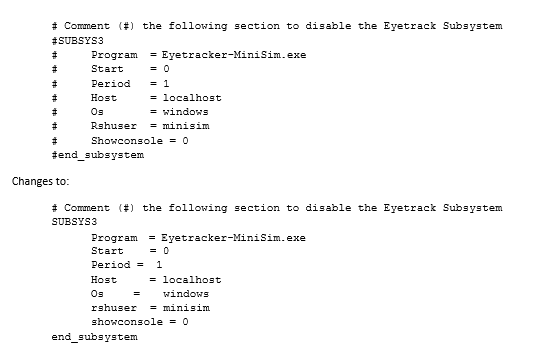
To enable the eye tracking subsystem, comment out using the # symbol the appropriate lines:
To disable the eye tracker, replace the # symbols.
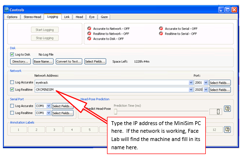
Next, setup the Face Lab eye tracking system itself. The eye tracker needs to connect to the miniSim over Ethernet. Connect the eye tracker PC to the MiniSim Pc through the use of an Ethernet switch (note the above diagram). Once the computer hosting Face Lab has been connected to the miniSim, now you need to instruct face Lab to forward data to the miniSim. This is done on the “Controls” dialog in face Lab, select the “Logging” panel. Select “Log Real-time”, under Network Address, type in the IP address of the miniSim. The port number should be set to 2020.
When doing ‘precision’ eye tracking in Face LAB 5.0, you must also set the eye tracker to log to disk.
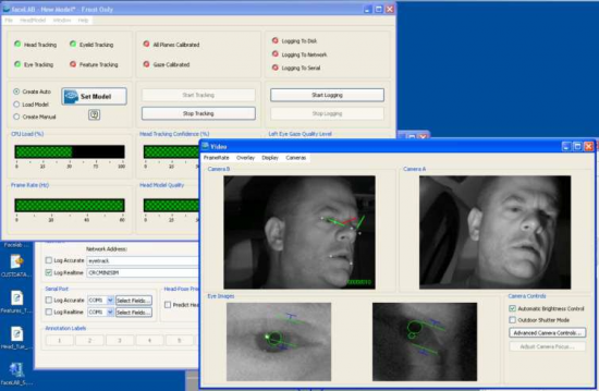
Once the communication between face Lab and the miniSim have been set up, you will need to start logging. Once a model has been setup, you hit the “Start Logging” button (as seen in the picture bellow) on the model dialog. This will start sending data to the MiniSim, and you should get Eye tracking data recorded in the DAQ file.
Eye Tracking Markers
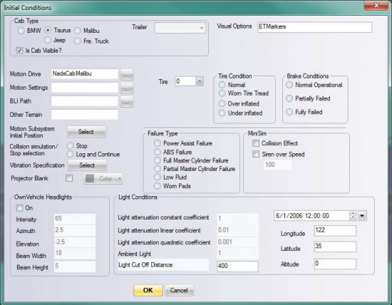
When the eye tracker is present and running, the system can display crosshairs that show where the driver is looking. This is helpful for eye tracker setup and system testing. See the section on the EyeTrackerScreenConfig.txt configuration file in the Configuration Files section of the manual to configure the screen geometry correctly – if you build a ‘world model’ inside FaceLab, the Screen location settings are the same. To turn on the eye gaze location markers on the miniSim display, add "ETMarkers" to the ’Visual Options’ string list when you author the scenario.
Eye Tracking Variables
The eye tracking variables are recorded in the DAQ file. They variable definitions are described below:
~Insert Eye Tracking Variable Description Here~
Serial Tilter
The Horita SCT-50 Serial Control Tilter is a device that overlays text data on a video image. The data is transmitted via a serial port from the PC to the Titler, hence the name ‘Serial Titler’. New PCs do not typically have a serial port, so a USB to Serial converter is used.
Install USB-Serial Converter Driver
Installation Instructions:
- Unzip PL2303_Prolific_DriverInstaller_v130.zip
- Run “PL2303_Prolific_DriverInstaller_v130.exe”
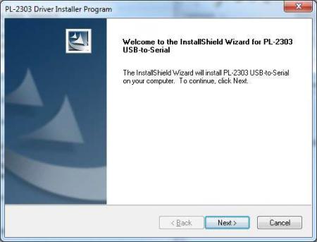
- Click “Next >"
- (Installer runs)
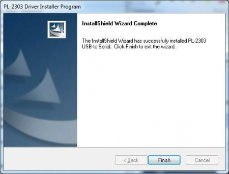
- Click “Finish”
- Reboot for good measure
- Plug in USB-to-Serial adapter
