Creating New Scenarios
ISAT User's Guide Table of Contents
Contents
Creating New Scenarios
This section describes how to build a new scenario. It is important to understand that a given scenario is always associated with a specific road network. As a result, the first step in creating a new scenario is selecting the road network on which this scenario will take place. Road networks are stored in files with the extension .bli.
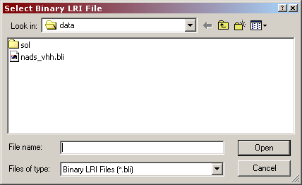
To create a new scenario select the File->New menu option. The dialog box shown in Figure 3-26 appears.
Select the appropriate road network and click on the Open button. After a brief delay (the delay will vary depending on the speed of the computer and the complexity of the selected road map), the road network will appear on the main window of the tool. It is now possible to author scenarios on that map.
Model and Object Pre-creation
During run-time operation, the simulator is very sensitive to processor or memory-intensive operations, including loading objects from the hard drive into memory. The effects of these operations typically exhibit as a momentary pause or 'hang', during which the display no longer updates. The duration of the hang can range from a few frames up to several seconds.
Fortunately it is possible to avoid these types of run-time hangs through "pre-creation". Objects are created by the scenario author at the beginning of each scenario they are required for. Their lifetime can be as short as 1 second; offsetting the creation time by .1-.2 seconds allows the simulator to process the pre-create object list efficiently. The pre-creation process will take a noticeable period of time, so it is necessary to inform the participant not to start driving until told do. On the MiniSim a message text can be displayed for this purpose, and then changed to “Begin driving..” after a pre-determined period of time.
Once an object has been created and then deleted, it is available in memory and the use of the object will not cause a creation hang later in the scenario. For multiple objects that share the same model type, only one pre-creation is needed on the MiniSim. The model will be loaded into memory after one pre-creation and multiple instances of it are created by duplication in memory instead of reading from the hard drive, so there will be no hangs.
Opening Existing Scenarios
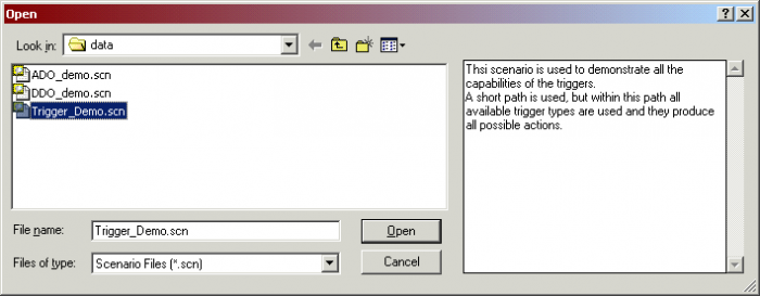
To open an existing scenario, use the industry default File->Open menu option or use the Ctrl-O shortcut key. The dialog box illustrated in
Figure 3-27 appears.
This dialog box is the typical file-selection dialog, with one exception. It provides a text area to the right of the directory listing. Once a scenario file is selected from the file list, the text area on the right shows the comments associated with the scenario.
Clicking on the Open button opens the specified scenario file.
You can zoom in closer to see more details or zoom further out to see a better overview of the map. In addition, the center of the screen can be changed (panned). There are several ways to navigate around the map.
A few navigation shortcuts are available on the navigation toolbar:
The leftmost button ensures that the left mouse button can be used to select elements as opposed to navigation. The second button places the tool in zoom mode. Zoom mode is indicated by the cursor shaped like a magnifying glass:
While in this mode, clicking the left mouse button (or rolling the mouse wheel backwards) on a location of the map makes that location the center of the screen and zooms closer to the scene. Repeatedly clicking on a point of interest can quickly zoom the view to that point. Clicking the right mouse button (or rolling the mouse wheel forward) anywhere in the map display zooms out but does not change the center of the screen.
The third toolbar button zooms and centers the map display so that it covers all scenario elements. This button is useful for quickly focusing on the area of the map where the current scenario is being developed.
The fourth toolbar button zooms and centers the map display so that it covers the entire road network.
The Follow Vehicle is the fifth button on the toolbar. It is only activated during rehearsal or monitoring mode. While in these modes, if the user selects one of the scenario elements in the virtual environment and then clicks on that button, the tool will maintain the same zoom but will pan the view port so that the selected element is always at the center of the screen. This functionality can be achieved also by double mouse click on the scenario element. This mode is useful for tracking a specific traffic element without having to adjust the map display continuously so the element is visible. If more than one element is selected before clicking the button, the view port will keep all of the selected objects in its view, panning or zooming out as necessary.
The sixth button, maintains the same zoom level, but pans the view so that the scenario start position is in the center of the display.
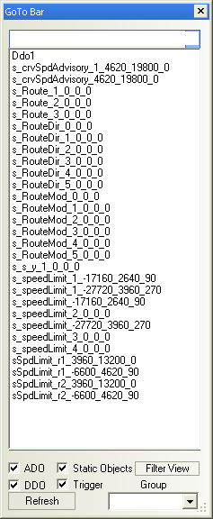
The button with the yellow question mark is used to bring up the find object window (Figure 3-29). Select the object from the list, click OK, and the view will pan putting that object in the center of the view field. The check marks at the bottom of the window filter the list. The refresh buttons refreshes the list and filter the list.
The check mark button brings up the verification tool. This tool checks the triggers for potential errors.
In any of the tool modes, the + and - keys located at the numeric row immediately above the main set of keys can be used to zoom in or out, respectively. Holding the Shift key while pressing + or - increases the amount of zooming performed at each button click.
The four arrow keys can be used to pan around the map. Again, holding the Shift key while pressing any of the arrow keys increases the amount of panning. Note that when clicking a particular arrow key, the map is re-centered as if the viewer has moved in the direction of the arrow key. For example, if the left arrow key is pressed, the map will be redrawn slightly to the left of its original position.
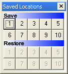
During scenario authoring, it is often useful to go back and forth between specific areas in the database. The ISAT provides the ability to save up to ten different viewpoints in the database and go between them by the click of a single button. To activate this functionality make sure the Saved Locations window is activated. To do so, selected, View->Saved Locations. The window shown in Figure X will appear. It contains two rows of numbered buttons. Buttons on the row titled “Save:” allow making a snapshot of the current view port. Buttons on the row titled “Restore:” allow returning to the respective viewpoint.
Note that initially all buttons on the Restore: row are grayed out, which indicates no viewpoint has been saved for the specific number. Once viewports are saved, the corresponding buttons on the Restore row become active. For example, in Figure 3-25 locations 1, 3 and 4 have memorized viewports.
To save the current viewpoint:
- Ensure the Saved Locations window is visible (click View->Saved Locations) if not.
- Click on any button on the Save: row (note that if the corresponding Restore: button is not grayed out, the previously saved viewport will be overwritten)
To return to a saved viewport:
- Ensure the Saved Locations window is visible (click View->Saved Locations) if not.
- Click on the button on the Restore: row that has the required viewport memorized
A smaller overview window that shows the whole map can be continuously displayed as a way to provide a top view of the whole database. Select menu View->Navigation Window to activate or de-activate display of the navigation window. When the navigation window is visible, a red rectangle within it shows the current boundaries shown in the main ISAT window. Dragging the rectangle in the navigation window dynamically adjusts the viewpoint of the main window allowing quick panning to specific areas in the database.
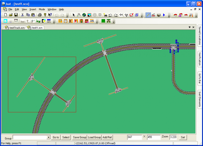
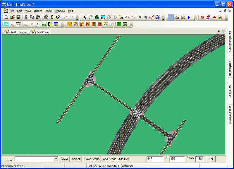
While not in zoom mode, the right mouse button can be used to draw a rubber band rectangle that the tool will automatically use as an area to zoom into. The tool computes a center point and zoom factor so that every part of the rectangle is visible.
For example, consider Figure 3-31. The left side illustrates the rectangle formed by clicking and then dragging the right mouse button, and the right side illustrates how the tool draws the map after the right mouse button is released.
Selecting and Editing Scenario Elements
Selecting elements
In edit mode, scenario elements can be selected either in isolation or in groups. Selection can only take place in the pointer sub-mode (as opposed to zoom mode). To select a scenario element, simply click on it. The selected scenario element will be drawn in a different way to indicate its selection status. In general, a thick red rectangle is drawn around its bounding box. To select more than one element at a time, click on the first element, and then click on additional elements while holding down the Shift key.
Editing elements
To edit a scenario element, double-click on that element, or by right-click on the element and selecting the Settings entry from the pop-up menu. Note that the actual menu will depend on the type of scenario element, but there will always be a Settings entry. After either double-clicking or selecting the Settings option, a modal dialog box reflecting the current settings of the scenario element will appear.
